 Neditek
1090 SAW Filter
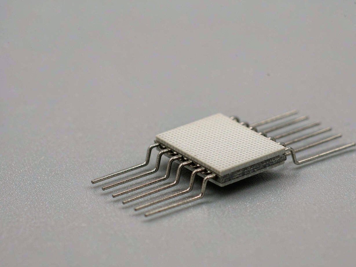
How acoustic surface waves are filtered
SAW is an abbreviation for Surface Acoustic Wave, which means acoustic surface wave. The SAW filter performs filtering by relying on sound waves propagating on the surface of the piezoelectric substrate: the radio frequency signal first becomes a sound wave on the surface, and after a period of propagation and interference, it becomes an electrical signal again. The interdigital transducer at the input converts the radio frequency voltage into sound waves, and the interdigital transducer at the output picks up the sound waves after propagation and interference into electrical signals. The period of the interdigitated electrode and the speed of sound on the piezoelectric material surface together determine the main operating frequency. The number of digits, aperture and reflective structure of the electrode together affect bandwidth, loss and suppression.
This approach brings two very practical benefits. First, the wavelength of sound waves is much shorter than that of electromagnetic waves of the same frequency, and SAW filters can make quite steep selectivity in very small packages. Second, interdigitated graphics are formed by photolithography, with high consistency in mass production and a fixed frequency response. Therefore, SAW filters have always been a common option in scenarios requiring miniaturized, high-volume, fixed-frequency filtering, such as mobile communications, GNSS, telemetry, broadcasting, and IoT front-ends.
1090 MHz frequency point
1090 MHz is a frequency point that is often singled out in RF filter selection. However, to obtain a 1090 MHz requirement, the first step is to expand the requirement into a complete frequency response template. The center frequency number itself only indicates the frequency point position and cannot replace key parameters such as passband width, stopband suppression system, port impedance and power tolerance; it also falls near 1090 MHz, and the actual requirements under different systems, different standards and regulations in different regions may vary greatly. After asking each of the upper and lower passband side frequencies, upper interpolation limit, stopband range, port form and power level, and then comparing them with specific models, we will not make the wrong choice of two devices with the same center frequency but completely different frequencies.
Specific specifications of a 1090 MHz SAW filter
It is more intuitive to put the above ideas into specific models. The NDF9019 has a center frequency of 1090 MHz, a bandwidth of 12 MHz, an insertion loss of 4 dB, and is packaged in QCC8B. The four things of center frequency, bandwidth, interpolation and packaging are put together to form a product specification that can be purchased and verified; if you place an order just because the center frequency falls at 1090 MHz, it will almost certainly be rolled back and rectified.
It is important to note that the 12 MHz bandwidth and 4 dB interpolation are hard indicators that must be compared with the system requirements when selecting a model, rather than optional reference values. If the actual passband of the system is wider than 12 MHz, or the link budget requires more stringent interpolation than 4 dB, you need to look for it in the SAW material number of the adjacent frequency point, rather than simply using NDF9019 as a general-purpose device.
Which parameters to look at when selecting a type
In the specification sheet of a SAW bandpass filter, the fields worth checking item by item usually include: center frequency, lower cutoff frequency, upper cutoff frequency, bandwidth and its definition point, insertion loss, return loss or standing wave ratio, in-band ripple, stopband suppression system, group delay, and whether it is a single-ended or differential port, nominal impedance, matching conditions, package ground, electrostatic level, Maximum input power and temperature derating. Insertion loss is represented by the S21 amplitude. The test must specify the direction, impedance, temperature, and reference surface. The stopband suppression system must be bound to a specific frequency or frequency range. The value of a single deepest notch point cannot represent the minimum suppression system of the entire segment. Acoustic filters also need to pay attention to group delay, which directly affects the amplitude and phase integrity of broadband modulated signals.
The power item is particularly easy to misread. The maximum power of an acoustic filter may be given separately in terms of continuous wave, peak, lifetime average power, or specific modulation waveform. The dBm or watts at different apertures cannot be simply converted. The power that can be carried in a short period of time is not equal to the long-term safe operation, and the peak wattage cannot be directly regarded as the continuous rated power.
Temperature, power and packaging are unavoidable limitations
SAW devices have several unavoidable physical limitations. The first is temperature. The speed of sound on a piezoelectric substrate will change with temperature, resulting in the center frequency and passband drifting together. For a receiving link that leaves a relatively tight passband, this drift may directly eat up the frequency margin. Temperature-compensated SAWs use cladding or composite structures such as silica to compress the frequency temperature coefficient, but the compensation layer also changes the acoustic boundaries, Q value, coupling and interpolation, and the manufacturing process is more complicated. The second is power. When operating at near-limit radio frequency power for a long time, the interdigital electrode will heat up, and metal migration or fatigue may occur, leading to increased plugging loss, frequency drift or even open circuit. The third is encapsulation stress. Temperature cycling, moisture intrusion or particle contamination will change the acoustic boundary and mechanical stress, causing the center frequency, loss and suppression to shift.
Therefore, when using the SAW filter at the board level, the grounding pad, impedance control, port orientation, matching elements, and adjacent traces must all be performed according to the recommended layout of the target model. When there is frequency deviation at the board level, pad, hole or trace parasites often bias the performance before the chip itself.
Back to the starting point of selection
When selecting frequency point products such as 1090 MHz SAW filters, the safest order is: first expand the system requirements into a complete frequency response template, and then use the fields of center frequency, passband, interpolation, stopband, power, impedance, port form and package form to compare candidate devices one by one; after confirming that they are met, then check the layout, temperature, reliability and supply status. This will neither lead to misselection due to an isolated center frequency number, nor will it obscure the true difference by individual typical values.