 Neditek
Baw Filter Vs Saw Filter: Key Selection Factors
In an RF front end, baw filter vs saw filter cannot be decided by technology name alone. Both are acoustic filters, but acoustic energy travels differently: SAW mainly propagates along the surface of a piezoelectric material, while BAW primarily resonates through the thickness of a piezoelectric film or within its bulk. Practical selection also depends on frequency, bandwidth, insertion loss, rejection, power, temperature stability, and package requirements.
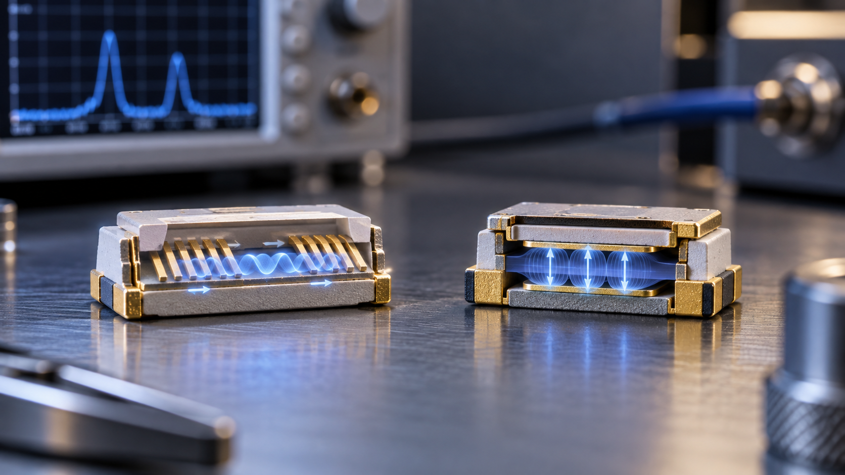
How SAW and BAW differ in operation
SAW filters use acoustic waves that travel along the surface of a piezoelectric material. Input and output interdigital transducers convert electrical signals to acoustic waves and back again. The electrode period and the material’s surface acoustic velocity influence the main operating frequency, while the aperture, number of finger pairs, and reflector structure affect bandwidth, loss, and rejection. This makes SAW suitable for fixed-frequency selection in a small package, including mobile communications, GNSS, remote control, telemetry, broadcast, and IoT front ends. Its trade-offs include temperature-related frequency shift, finite power handling, sensitivity to package stress, and tighter electrode-dimension requirements at higher frequencies.
BAW filters use acoustic resonance through the thickness of a piezoelectric film or within its bulk. Common implementations include FBAR and SMR. BAW is often considered when a design places greater emphasis on higher frequency, higher Q, temperature stability, or power handling. This is a selection tendency rather than a performance guarantee for every device. Final results still depend on topology, coupling, and packaging.
Center frequency is not a complete specification
Consider two 315 MHz products. NDF3025 has a 4.6 MHz bandwidth, 1.5 dB insertion loss, and a QCC8B package. NDF420 also operates at 315 MHz, but its bandwidth is 0.6 MHz, insertion loss is 3 dB, and its package is QCC8C. The center frequency is the same, while the passband, loss, and package are different.
In a baw filter vs saw filter comparison, first fix the target frequency, system bandwidth, and power conditions. Then check the passband and stopband before comparing bandwidth, insertion loss, rejection, VSWR, ripple, and group delay. Q can provide a useful clue about resonator selectivity. Under otherwise similar conditions, a higher Q can support lower loss or steeper selectivity, but Q alone does not represent the complete performance of the finished filter.
Power and temperature shape the trade-offs
For a transmit chain, power cannot be reduced to a single wattage value. Average power, peak power, operating waveform, mismatch, heating from insertion loss, temperature, and connector ratings can all affect the decision. BAW may be included as a candidate when higher power or temperature stability is important, but the specific result still has to be checked under comparable conditions.
SAW is commonly suited to fixed-frequency, compact front ends. When a design places more emphasis on higher frequency, high Q, temperature stability, or power conditions, BAW can be evaluated in parallel. If the available information contains only a center frequency or a “SAW/BAW” label, the selection basis is incomplete, and it is not enough to establish that two specific devices are interchangeable.