 Neditek
Difference Between PIN Diode and Avalanche Photodiode
In an optical receiver, a PIN photodiode and an avalanche photodiode (APD) both turn incident light into an electrical signal. The practical difference is whether the device multiplies the photocurrent internally. The term “PIN diode” also needs context: an RF PIN diode has a P-I-N structure, but uses bias to control RF impedance. Its switching specifications cannot stand in for photodetector specifications.
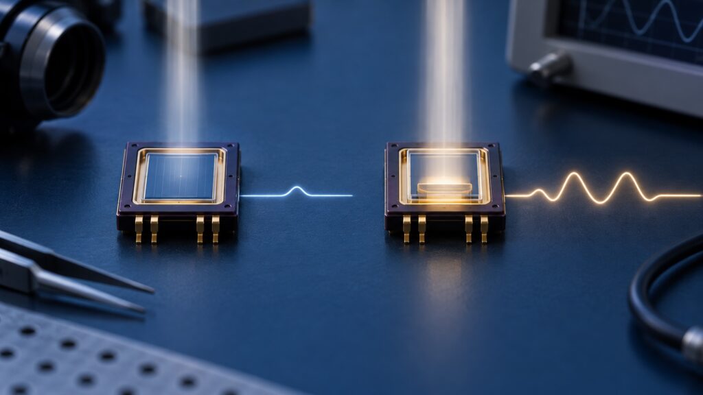
How the Two Detectors Produce an Output
The nearly intrinsic region of a PIN photodiode creates a relatively wide depletion region. When light generates electron–hole pairs, reverse bias helps collect them as a current related to the incident light. An ordinary PIN photodiode generally has no internal avalanche gain. The receiver therefore has to provide enough downstream amplification while keeping its own noise under control.
An APD also starts with photogenerated carriers. Under a stronger reverse electric field, those carriers can trigger impact ionization and multiply the current inside the device. This gain can help in some weak-light conditions, but multiplication also adds noise. A larger output current does not automatically mean a better system signal-to-noise ratio; the result depends on optical signal strength, receiver noise, and operating conditions.
Bias and Temperature in the Design
Both devices must be assessed at their specified reverse bias and operating conditions. To obtain avalanche gain, an APD typically needs a higher, more stable reverse bias and closer attention to temperature and breakdown limits. A fair comparison includes the bias supply, temperature management, and control circuitry—not just the detector chip.
A PIN photodiode avoids that multiplication-control requirement, but a simpler detector circuit does not guarantee adequate performance in low light. When the received signal is already strong enough, or downstream noise is well controlled, internal gain may offer little practical benefit. Near the receiver threshold, compare the APD’s gain advantage and multiplication noise at the same intended operating point.
What to Check Before Choosing
Start with the wavelength or radiation to be detected, the actual incident signal level, and the required bandwidth. Then compare spectral response, dark current, terminal capacitance, noise, active area, and reverse voltage under relevant conditions. No single sensitivity claim captures the entire receiver design. For a demanding bandwidth, consider capacitance together with the following circuit rather than assuming either device type is inherently faster.
For an APD, verify that gain, noise, and temperature behavior meet the requirement at the planned bias, and that the system can hold that bias stable. For a PIN photodiode, check whether the output current leaves enough margin at the actual light level and downstream noise floor. When comparing cost, include the bias and control circuitry as well as the detector itself.
Do Not Confuse an RF PIN Diode with a Photodetector
RF PIN diodes are commonly specified by forward series resistance, off-state capacitance, isolation, insertion loss, and power handling. An optical PIN detector is assessed by spectral response, dark current, active area, noise, and detection bandwidth. They share a P-I-N layer arrangement, but their design goals differ. NEDITEK’s RF PIN selection guide lists parts for switching, attenuation, and limiting; that listing does not establish their suitability for optical reception. Likewise, an alternative part number containing the letters “APD” must not be mistaken for an avalanche photodiode.
When evaluating the difference between PIN diode and avalanche photodiode, first establish that “PIN” means an optical detector. Then decide whether internal gain is needed at the actual wavelength, signal level, bandwidth, bias, and noise limits. Make the final choice from complete specifications for the candidate parts and tests under the intended system conditions.