 Neditek
What Is A Rf Filter? Types, Uses, And Selection
An RF filter is a circuit or component that passes selected radio frequencies while attenuating others. In a receiver, it can reduce unwanted signals before they reach sensitive stages. In a transmitter, it can suppress unwanted frequency components. Its job is frequency selection, and its usefulness depends on how well its response fits the signal and the surrounding interference.
For an engineer asking “what is a rf filter,” the practical starting point is a frequency plan: which frequencies must pass, which must be reduced, and how much loss the useful signal can tolerate. A center frequency alone cannot describe those requirements.
How An Rf Filter Separates Signals
A filter has a frequency-dependent transmission response. The region intended to carry the useful signal is the passband. A region that must be attenuated is a stopband. Between them lies a transition region, where attenuation changes rather than jumping instantly from low loss to strong rejection.
That transition matters when an unwanted signal sits close to the useful band. A component may pass the desired center frequency yet provide too little attenuation at a nearby interferer. Conversely, a very narrow response may reduce interference while also attenuating part of the wanted signal.
Read the passband and stopband limits together. The useful signal needs enough room for its occupied bandwidth and frequency tolerance, while the unwanted frequencies need specified attenuation at their actual locations.
The Main Rf Filter Types
A low-pass filter passes frequencies below its cutoff region and attenuates higher frequencies. It is commonly used to reduce harmonics or limit high-frequency noise. A useful specification states both the upper passband limit and the higher-frequency range where rejection is required.
A high-pass filter passes a higher-frequency region and attenuates lower frequencies. Its selection still needs boundaries: the low-frequency stopband, the transition region, and the upper end of the usable passband. “Passes high frequencies” is too broad a requirement for choosing a component.
A bandpass filter passes a defined band and attenuates frequencies on both sides. This is useful when a receiver or another RF stage needs a particular frequency window. Center frequency, lower and upper band edges, and bandwidth belong together in the specification.
A band-stop filter attenuates a defined region while preserving useful transmission on either side. For a narrow rejection requirement, the notch center is only part of the description. Stopband width, minimum attenuation, and loss in the neighboring passbands also matter.
These names describe the response. They do not tell you the physical technology, package, power rating, or complete frequency behavior.
Saw, Baw, Mmic, And Other Implementations
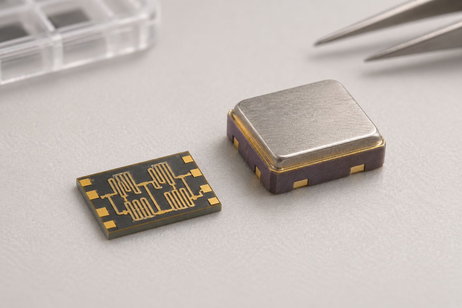
A SAW filter uses acoustic waves traveling along a piezoelectric surface. Interdigital transducers convert between electrical signals and acoustic waves. This allows frequency-selective behavior in a compact component.
A BAW filter uses acoustic resonance through a piezoelectric film or within its volume. SAW and BAW are both acoustic approaches, but choosing between them requires the actual frequency response, loss, power, temperature, and size specifications of the candidate devices.
MMIC filters provide another implementation category. Neditek’s filter selection guide includes MMIC low-pass filters as well as MEMS and SAW filter categories. That gives useful context for comparing component forms, but a category name does not establish that a particular part meets a system requirement.
Cavity filters use electromagnetic resonance in metal cavities or coaxial structures. They can suit applications needing low loss, strong selectivity, or higher power, though size and weight may limit their use in compact equipment.
Response type and technology should therefore be considered separately. Start with the required passband and stopbands, then assess which implementation can meet them within the available space and operating conditions.
The Specifications That Change The Choice
Insertion loss describes how much the useful signal is reduced when the filter is inserted. Lower loss is valuable, especially before a low-noise amplifier, where passive loss enters the receiver noise budget. Still, a low-loss device is not useful if it fails to reject the unwanted frequencies.
Stopband rejection must be tied to a frequency or range. A single deep notch on a curve does not establish minimum rejection across a broad stopband. Compare the specified attenuation where your interferers actually occur.
Bandwidth also needs a definition. A stated minus-three-decibel bandwidth is not automatically a guarantee of acceptable loss or ripple throughout the signal’s required passband. Check the limits used by the data sheet and compare them with the signal bandwidth.
Passband ripple describes variation in transmission across the useful band. Group-delay variation concerns how delay changes with frequency. Both can affect wideband or phase-sensitive signals, so insertion loss alone cannot establish signal fidelity.
Return loss or VSWR describes port matching. Confirm the specified impedance and whether the ports are single-ended or differential. Matching networks and grounding conditions are part of the application requirements, rather than details to infer from package size.
Finally, check temperature and power conditions. A room-temperature response does not establish the passband edges over the full operating range. Likewise, a short-term survival rating does not establish allowable continuous operating power. Average power, peak power, waveform, and thermal conditions can lead to different limits.
Where The Filter Belongs In The Signal Chain
A receiver-front-end filter can reduce out-of-band signals before they reach the LNA. The tradeoff is that its insertion loss also reduces the wanted signal before amplification. The appropriate response balances interference rejection with the receiver noise budget.
In a transmit path, the priorities may shift toward harmonic suppression, power handling, mismatch, and heating. A filter selected for a small-signal receiver should not be assumed suitable for a transmitter simply because the frequencies overlap.
After frequency conversion, filtering can select the intended mixing product. Here too, the required passband and unwanted frequencies should be defined at that point in the chain, rather than copied from the antenna specification.
A Practical Way To Specify An Rf Filter
Begin with the useful frequency range and its tolerances. Mark the unwanted frequency ranges and the minimum attenuation needed in each. Then state the maximum acceptable passband loss, ripple, and matching limits.
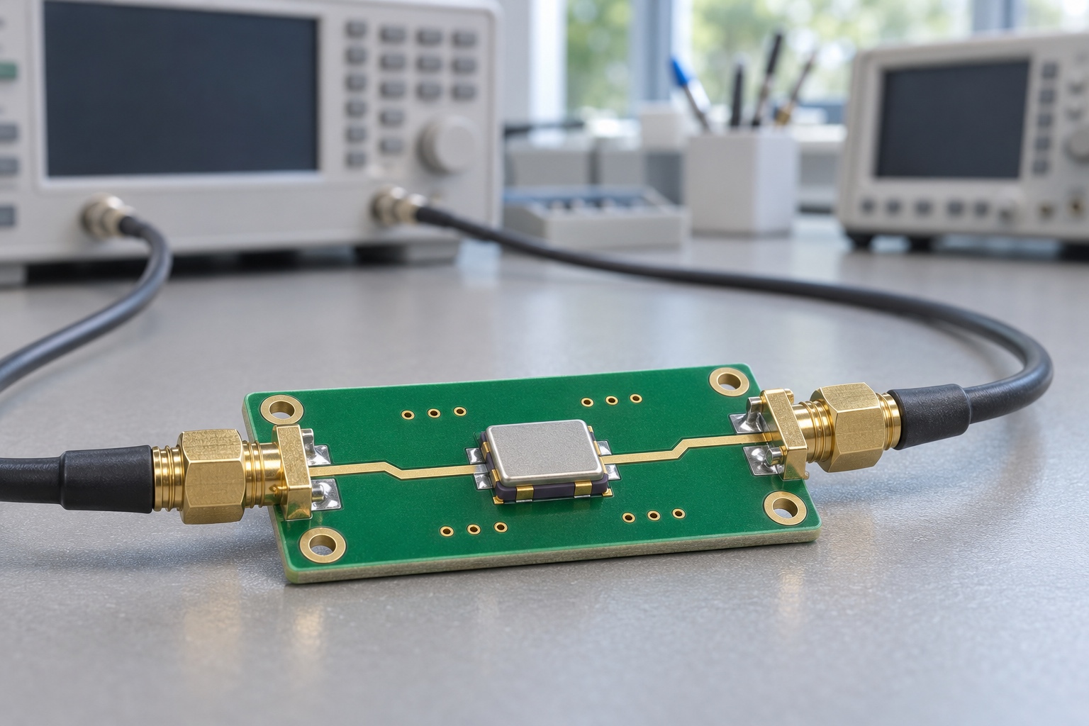
Add the operating temperature, port configuration, power conditions, and package constraints. For modulation-sensitive applications, include group-delay requirements. Request the relevant response curves or S-parameter data with their measurement conditions and reference planes.
When discussing a candidate with Neditek, use that complete requirement set to guide the comparison. Confirm the current data sheet and part status before treating a selection-guide entry as an approved choice. The right RF filter is the one whose specified response preserves the useful signal and provides the required rejection under the conditions in which the circuit will operate.