 Neditek
How Do Schottky Diodes Work? From Barrier To RF
A Schottky diode works through a barrier formed where a metal contacts a semiconductor. With forward bias, majority carriers cross that barrier and current flows. With reverse bias, the junction restricts conduction, although some leakage remains. This structure gives Schottky diodes their characteristic combination of relatively low forward voltage and fast response.
How do Schottky diodes work in a radio-frequency circuit? The same junction does more than pass current in one direction. Its nonlinear current-voltage response lets a detector extract a lower-frequency signal from an RF input, or lets a mixer generate new frequencies. Understanding that connection helps explain why a small RF detector diode and a power rectifier can share the Schottky name while requiring very different specifications.
What Happens At The Metal-Semiconductor Barrier
The rectifying junction in a Schottky barrier diode is a metal-semiconductor contact, rather than the P-N junction used in a conventional junction diode. The barrier controls how readily carriers cross the interface.
For an N-type device, electrons are the majority carriers. Forward bias makes it easier for them to cross the interface, so the forward current rises as voltage increases. Reverse bias opposes that flow. The device still has reverse leakage and a finite reverse-voltage limit; treating it as a perfect one-way switch leaves out both constraints.
The forward voltage is also not a fixed turn-on point shared by every Schottky diode. A quoted value belongs to a particular device at a stated current and temperature. To compare two parts, read those conditions alongside the number. A low-voltage reading at a small test current does not describe the voltage drop at every operating point.
Why The Response Can Be Fast
Schottky conduction relies on majority carriers and avoids the minority-carrier storage mechanism associated with a forward-biased P-N junction. That is an important reason Schottky devices suit fast rectification and high-frequency signal processing.
It does not make the device electrically instantaneous. Junction capacitance, series resistance and package parasitics still affect its behavior. In an RF circuit, the junction and the connections around it must be considered together. A diode with a low forward voltage may still be unsuitable for the intended frequency or signal level.
This is also why a power Schottky rectifier should not be selected as an RF detector simply because both devices switch quickly. The rectifier needs current-handling and thermal ratings appropriate to its power path. The detector needs electrical characteristics appropriate to a small, rapidly changing signal.
How A Schottky Detector Uses Nonlinearity
In a resistor operating linearly, current changes in proportion to voltage. A Schottky diode has a curved current-voltage relationship. An RF voltage applied around its operating point therefore produces a nonlinear current response that a detector circuit can use to obtain a lower-frequency output.
For example, an amplitude-modulated RF signal has a rapidly oscillating carrier and a more slowly changing envelope. A suitable Schottky detector circuit can recover that envelope as a baseband, or video, signal. Here, “video” describes the detector’s lower-frequency output; it does not necessarily mean a picture signal.
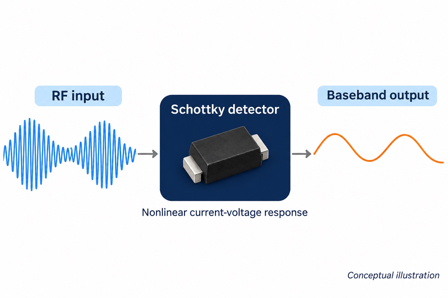
The diode is one part of that circuit. Bias, matching and the output network help determine the result. Some detector devices are intended for zero-bias operation, while others use an applied bias. “Schottky” alone does not tell you which arrangement to build.
When comparing detector diodes, check sensitivity at the stated frequency, input power and bias. Capacitance and series resistance also matter. A sensitivity figure measured under different conditions cannot establish which part will perform better in the intended circuit.
How Mixing Uses The Same Junction
A mixer applies an RF signal and a local-oscillator signal to a nonlinear element. The interaction produces sum and difference frequencies. The circuit selects the desired output, such as an intermediate frequency in a receiver.
A Schottky mixer diode uses the junction’s nonlinear conductance for this frequency conversion. It does not perform the same job as an amplifier: the purpose is to move a signal to another frequency. Local-oscillator drive, diode arrangement and port conditions belong in the selection process.
Barrier height is part of that decision. Lower-barrier devices can suit circuits with limited drive, while higher-barrier options may be appropriate where signal handling and distortion are more demanding. Neither choice is universally better. Compare the proposed diode under the actual RF and local-oscillator conditions.
Why The Package Matters
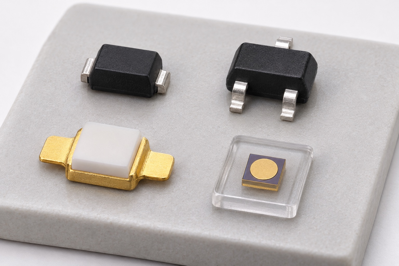
RF Schottky devices appear as bare chips, beam-lead chips, metal-ceramic packages and plastic surface-mount parts. These forms create different assembly and interconnection requirements. Package choice therefore belongs alongside the electrical comparison, rather than being left until the board layout is complete.
A three-terminal package needs particular care. It may contain a common-anode pair, a common-cathode pair, a series pair or another arrangement. Some three-terminal parts contain only one diode with an unused or otherwise connected terminal. The outside shape cannot establish the internal circuit.
For a replacement, compare the complete part number, internal connection diagram and pin assignments before considering electrical equivalence. A mechanically compatible package can still connect the wrong junction to the circuit.
What To Check For Your Application
For power rectification, review the reverse-voltage rating, forward current, surge rating, forward voltage at the required current, leakage and thermal limits. Keep the operating temperature in the comparison. A forward-voltage advantage is useful only when the device also meets the circuit’s voltage and thermal requirements.
For RF detection, define the frequency band, expected input-power range, bias arrangement and required output response. Then compare sensitivity, capacitance, series resistance and package details under relevant conditions.
For mixing, add the local-oscillator drive, circuit configuration and conversion requirements. If the circuit uses a diode pair, check matching and internal topology as well as the ratings of each junction.
For a discussion with Neditek, provide those operating conditions and the intended package or assembly method. They give the component comparison a useful starting point: a specific circuit duty, with the barrier, electrical ratings and physical connection assessed together.