 Neditek
How Do Image Intensifier Tubes Work? A Practical Guide
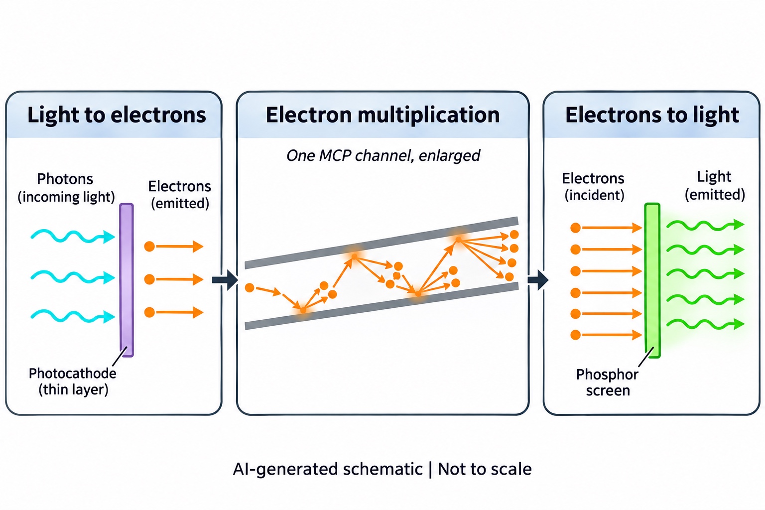
A faint scene becomes visible through a sequence of conversions inside an image intensifier tube: incoming light releases electrons, those electrons are multiplied, and a phosphor screen converts them back into light. The process takes place inside an evacuated enclosure.
So, how do image intensifier tubes work in a low-light imaging system? Following the signal through a typical microchannel plate design explains both the brighter output and the limits that still matter when choosing a tube.
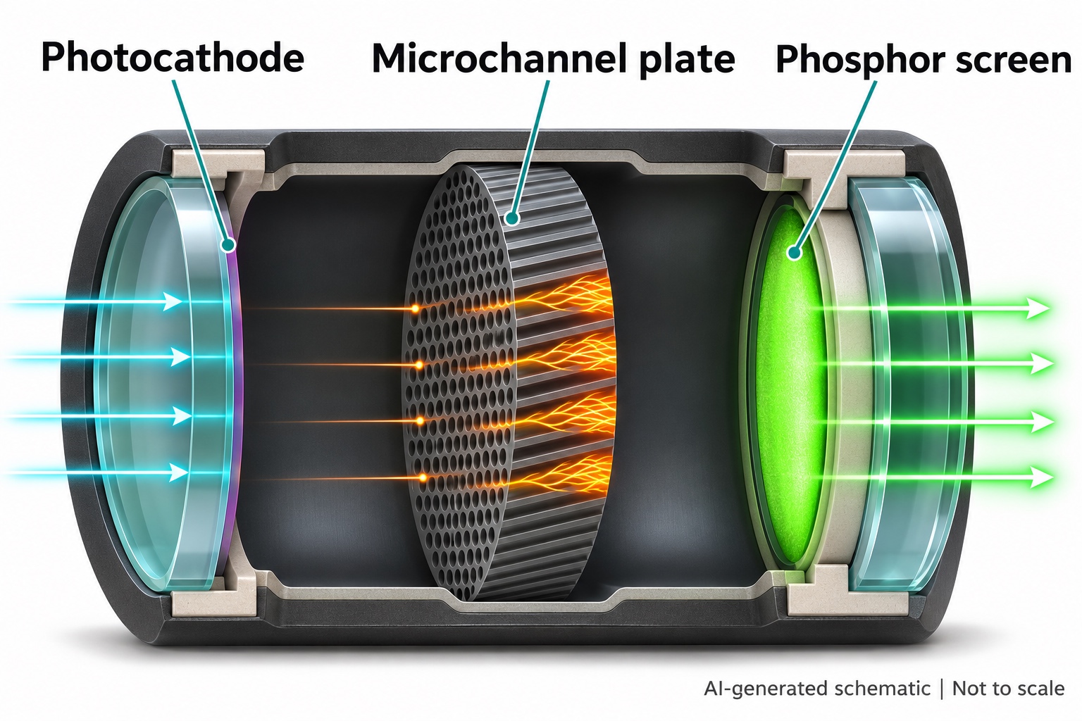
The Photocathode Turns Incoming Light Into Electrons
The input window admits light to a photosensitive layer called the photocathode. Absorbed photons can release photoelectrons into the vacuum. An electric field then draws these electrons toward the next stage.
This conversion is wavelength dependent. The input window must transmit the light of interest, and the photocathode must respond to it. Quantum efficiency describes the ratio of emitted photoelectrons to incident photons. It is therefore useful to compare response at the intended wavelength rather than rely on a general sensitivity claim.
The photocathode also contributes dark noise through thermally generated electrons. A useful comparison considers sensitivity together with background noise, particularly when the incoming signal is weak.
The Microchannel Plate Multiplies The Electron Signal
A microchannel plate, usually shortened to MCP, contains many narrow channels. With a voltage across the plate, electrons accelerate along these channels. Collisions with the channel walls release secondary electrons, which can produce further collisions and multiplication.
The larger electron population leaving the plate carries the amplified signal toward the output screen. MCP gain depends on the operating conditions, including the voltage applied across it. A gain figure is meaningful only alongside the tube configuration and its specified conditions.
This description applies to MCP-based tubes. Earlier first-generation image intensifiers used a different construction without an MCP, so this component should not be presented as universal to every image intensifier ever made.
The Phosphor Screen Produces The Visible Output
Electrons leaving the MCP strike a phosphor screen, which emits light. An output window passes this intensified optical image onward. In a camera system, a fiber-optic or lens coupling transfers the image to the sensor while maintaining its spatial arrangement.
The screen also has a time response. Its light does not necessarily disappear immediately after excitation ends. For rapid sequences, phosphor decay must suit the readout timing to limit afterimages. The output window and phosphor should therefore be considered with the intended viewing or camera arrangement.
Gain And Gating Do Different Jobs
Gain controls amplification. Gating controls when the intensifier accepts the electron image. In a suitably equipped tube, changing the potential between the photocathode and MCP input allows photoelectrons to reach the plate or prevents them from doing so. This creates an electronic exposure window.
Such gating is useful for capturing brief events. It is an optional capability with product-specific timing, not a feature to assume from the words image intensifier alone.
More Amplification Is Not Automatically A Better Image
For an intensified camera, sufficient gain can raise a weak signal above the sensor read-noise floor. Excessive gain can reduce usable dynamic range. The practical aim is to obtain adequate amplification while retaining room for brighter parts of the image.
Photocathode efficiency, internal noise, phosphor efficiency, optical coupling and sensor response all affect detection. Comparing only maximum gain leaves much of the imaging chain unexamined.
What To Confirm Before Selecting A Tube
For a Neditek product inquiry, describe the light to be observed, the intended wavelength range and whether the output will be viewed directly or coupled to a camera. If timing matters, specify the event duration and ask whether gating and the phosphor response suit that task.
Request the current datasheet for the exact model to confirm its structure, spectral response, gain conditions, output arrangement and supported operating settings. The general conversion process explains how an MCP-based tube functions; those model-specific details determine whether it fits the imaging system.