 Neditek
What Is A Rf Filter? Key Types, Uses & How It Works
A radio frequency (RF) filter is 1 specialized hardware component that lets specific radio frequencies pass through a circuit while blocking or absorbing unwanted signal interference. If you ask a hardware engineer “what is an RF filter in practice”, they will tell you that it is the last line of defense against signal noise.
Many hardware teams tend to pay little attention to RF filters in the design phase and treat them as dispensable vassals. This oversight has resulted in approximately 60 percent of new Internet of Things (IoT) and wireless devices failing their first FCC or EMC compliance tests. The specification of the filter must not be guessed. This guide will detail for you how these components work, which types are specifically needed for your project, and those sourcing guidelines that are enough to ruin a product release.
How Do RF Filters Work? The “VIP Bodyguard” Theory
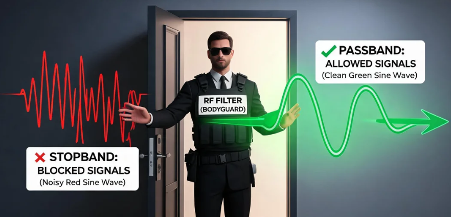
The core of the hardware architecture relies on frequency separation. If you want to really understand what a RF filter is, you might as well borrow the “VIP bodyguard” theory.
Imagine an upscale nightclub with a bouncer at the door holding a 1 specific guest list. They will have VIPs swaggering in while physically keeping uninvited guests out. RF filters do the same thing with electromagnetic waves.
The “VIP list” here is your passband (Passband)-that is, the specific frequency range that your device needs to actually send or receive data, such as the Wi-Fi 2.4 GHz. Filters ensure that these signals pass through with minimal energy loss. And those uninvited guests represent the stop band (Stopband). They may be interference signals from nearby towers, Bluetooth devices, or power supplies. The filter is now a bodyguard, attenuating (weakening) these excess frequencies to ensure that they never get close to your fragile receiving chip.
4 Core RF Filters (And Their Application Scenarios)
Engineers typically classify RF filters based on the frequency bands they are allowed to pass through. If you choose the wrong type, the hardware will definitely fail.
Low-pass and high-pass filters
Low-pass filters (LOW-pass filters) only allow signals below a certain cutoff frequency to pass through and block all signals above that frequency out the door. Audio engineers and radio designers often use it to eliminate high-frequency hiss, or to prevent high-order harmonics from splashing into adjacent channels.
High-pass filters (High-pass filters) are the exact opposite. They are responsible for intercepting low-frequency noise (such as the 60 Hz AC sound generated by power lines) and allowing high-frequency signals to reach the antenna smoothly.
Bandpass and bandstop (notch) filters
Band-pass filters (Band-pass filters) are the most common type used in wireless communications. They only allow a specific one “slice” frequency to pass through, while shielding all other frequencies up and down this range. There are dozens of bandpass filters hidden in your smartphone, specifically designed to isolate 5G signals from Wi-Fi signals.
Band-stop filters (often called notch filters, Notch filters) focus on “precision strikes” a specific troublesome frequency. Notch filters are commonly used by radar operators to shield a known, extremely destructive local interference signal without affecting other normal operations.
RF Filter Types Comparison
| Filter Type | What It Passes | What It Blocks | Primary Use Case |
| Low-pass | Signals below a specific cutoff frequency | Everything above the cutoff frequency | Eliminating high-frequency hiss or preventing high-order harmonics from bleeding into adjacent channels |
| High-pass | High-frequency signals | Low-frequency noise (e.g., 60 Hz hum from power lines) | Blocking low-frequency hum to let high-frequency signals reach the antenna |
| Band-pass | A specific “slice” of frequencies | Everything both below and above the specific slice | Isolating specific signals in wireless communication (e.g., separating 5G signals from Wi-Fi) |
| Band-stop | All frequencies except the targeted problematic frequency | One specific problematic frequency | Targeting and destroying a highly disruptive local jamming signal without affecting other operations |
Advanced Filter Technologies: SAW, BAW And Cavity Filters
To truly understand RF filter technology, you have to look at the physical materials inside the components. If you choose the wrong underlying technology in your actual operating environment, it is useless to memorize the dictionary definitions.
SAW (Sound Surface Wave) Filters: SAW components have an absolute dominance in the low frequency market below 2 GHz. They can convert electrical signals into sound waves on the surface of piezoelectric crystals. These filters are very affordable and work very well in GPS and older cellular network bands.
BAW (Bodular Acoustic Wave) Filter: BAW filters maintain extremely high operating efficiency between 2 GHz and 6 GHz. The advent of the 5G era forced manufacturers to turn to BAW because SAW filters would experience severe performance dips in high-frequency bands. BAW filters have better heat resistance and steeper stopband attenuation (cleaner filtering), making them a necessity for modern Wi-Fi 6 and 5G hardware.
Cavity Filters: Cellular base stations and heavy military radar facilities rely primarily on cavity filters. They are large metal boxes made by machining and are capable of withstanding extremely large transmit powers (often hundreds of watts). This level of power hits tiny SAW or BAW chips and melts them in an instant.
“3-T” Selection Matrix: A Pit-Saving Guide For Engineers And Procurement Experts
Purchasing teams often buy the wrong RF filters just by looking at the price tag. To this end, I have summarized a “3-T selection matrix” that aims to perfectly align engineering needs with actual procurement.
Target Frequency and Bandwidth (Target Frequency and Bandwidth)
You must specify both the center frequency and the required bandwidth. If you buy a narrowband filter in a broadband application, your data throughput will be severely “choke”, resulting in an alarmingly slow connection.
Tolerable Loss (insertion loss)
Any filter will inevitably absorb a portion of the “useful” signal, which is called insertion loss. Insert filters with excessive loss and force your transmit amplifier to double down. This will allow batteries in IoT devices that would have lasted for years to be drained in just a few weeks. It is important to keep the insertion loss within 2 dB, when conditions permit.
Thermal Limits / Temperature Drift (Thermal Limits / Temperature Drift)
Temperature changes the physical properties of the filter. A component that performs perfectly in a 25°C lab can have its frequency response distorted beyond recognition once thrown into a 60°C industrial warehouse. Remember: Always check the Frequency Temperature Factor (TCF) carefully on the data sheet.
3 Expensive Selection Myths That Ruin Hardware Projects
Most novice engineers and project managers fall into the same few predictable pits.
Blindly pursue the ultimate suppression rate and sacrifice insertion loss. Many engineers will force out out-of-band suppression rates of up to 60 dB on their data manuals. Component manufacturers can indeed make it, but the cost is to add more filter stages. The more stages there are, the greater the insertion loss. The end result: you do get a perfectly isolated signal, but it’s so weak that the antenna can’t even broadcast it.
No visual impedance matching. The RF filter must match the impedance of the surrounding circuit (typically 50 ohms). If you shove an impedance-mismatched filter directly onto the PCB board, you will create a signal reflection. Radio waves bounce back onto the transmitting chip, directly burning the circuit.
Ignore component size limits. BAW and SAW filters are only fingertip-sized, while ceramic and cavity filters take up extremely much onboard space. If the decision to switch to ceramic bandpass filters is made at an ad hoc stage later in the design cycle, the entire PCB layout team will basically have to start over.
Frequently Asked Questions (FAQ)
What is the difference between RF filter and duplexer?
RF filters can only isolate specific frequencies in a single direction. A duplexer is a component that combines two bandpass filters (one for transmission and one for reception) into one. It is with this that devices like smartphones can send and receive data simultaneously through a single antenna.
Can I use active filters in RF applications?
Engineers rarely use active filters in high-frequency RF applications (these filters require external power and use operational amplifiers). When operational amplifiers process signals above a few hundred megahertz, it is extremely difficult to avoid introducing severe noise. Therefore, passive filters (made of inductive, capacitive or acoustic materials) remain an absolute standard in the RF field.
How to measure the performance of RF filters?
Hardware technicians typically use a vector network analyzer (VNA) to measure performance. The VNA sends a sweep signal to the filter and plots exactly how much signal passes through (S21 parameter) and how much signal is reflected back (S11 parameter).
What happens if my RF filter breaks?
Once RF filters fail, they often completely paralyze communications. The receiving chip is overwhelmed by broadband noise and cannot decode the expected packets at all. In high-power transmitter applications, filter failure can lead to illegal out-of-band radiation, resulting in sky-high fines from regulators such as the FCC.
Why are RF filters in 5G devices so expensive?
5 G networks operate on frequency bands that are unusually crowded and very close together. To isolate these signals, BAW technology must be used, which involves an extremely complex piezoelectric manufacturing process. The stringent requirements for microscopic accuracy in high-frequency environments result in a cost per piece that is significantly higher than that of old-fashioned 3G/4G components.