 Neditek
Automotive SiC MOSFET Selection: What To Check First
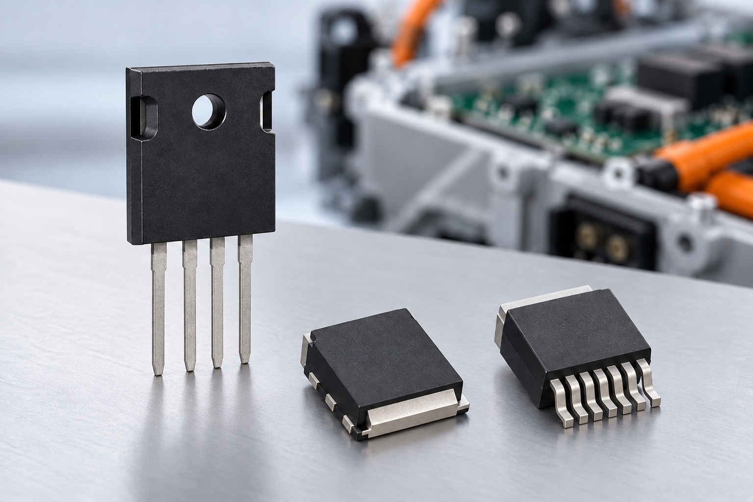
Choosing an automotive SiC MOSFET starts with a real operating profile, not a single headline rating. A device that looks attractive at 25°C may behave differently once bus voltage rises, current changes direction, and the cooling system reaches its normal working temperature. For a traction inverter, onboard charger, or DC-DC converter, the useful question is whether one part can meet the electrical, thermal, mechanical, and qualification requirements of that particular design.
Begin With The Voltage The Device Will Actually See
The DC bus value is only the starting point. Switching overshoot, regeneration, fault events, and stray inductance can raise the voltage across the MOSFET above the nominal bus. Define the normal and worst-case drain-source voltage at the device terminals, then check the candidate's VDSS rating against that envelope.
Neditek's automotive SiC MOSFET selection guide lists 650 V, 750 V, 1200 V, 1500 V, and 1700 V options. Those categories help narrow a shortlist, but they do not assign a voltage class to every 400 V or 800 V vehicle design. The required margin depends on the topology and measured transients. A higher rating is not automatically the better choice if it changes the resistance, charge, package, or cost balance.
Compare Losses At The Intended Operating Point
RDS(on) is important because it affects conduction loss, yet a 25°C figure alone cannot describe a converter's efficiency. Check how resistance changes with junction temperature and which gate voltage was used for the published value. Then compare switching behavior at the expected bus voltage, current, switching frequency, and gate resistance. Total gate charge, output capacitance, and the reverse-conduction path also matter, especially where current flows during dead time.
The catalog illustrates why a part-number comparison is more useful than a broad product-family claim. It lists NDS060001 as a 750 V, 15 mΩ device in TO-247-4, while NDS060010 is listed as a 1200 V, 12.5 mΩ device in TO-247-4. Their ratings are not a direct performance ranking: each value needs its stated test conditions, and the application must still be checked for switching loss and heat. Confirm the current data sheet and product status before using either part in a design.
Treat The Package As Part Of The Circuit
An automotive SiC MOSFET is selected for the assembly it will live in. Neditek's guide includes TO-247-3, TO-247-4, TO-263-7, TOLT, QDPAK, and HU3PAK options across its automotive range. Package choice affects mounting, heat removal, gate-loop layout, and power-loop parasitics. A four-lead package may offer a separate source sense connection for the driver, while a surface-mount option may suit a different board and cooling arrangement. Check the exact pinout and recommended layout for the selected part; package names alone do not establish interchangeability.
For a practical comparison, draw the full thermal path from junction to coolant or ambient air. Include the package interface, mounting method, heat spreader, and realistic cooling conditions. Then measure switching overshoot and ringing on the intended board. A low-resistance part cannot deliver its expected benefit if the assembly makes it difficult to control temperature or switching transients.
Build The Gate Drive Around The Selected Device
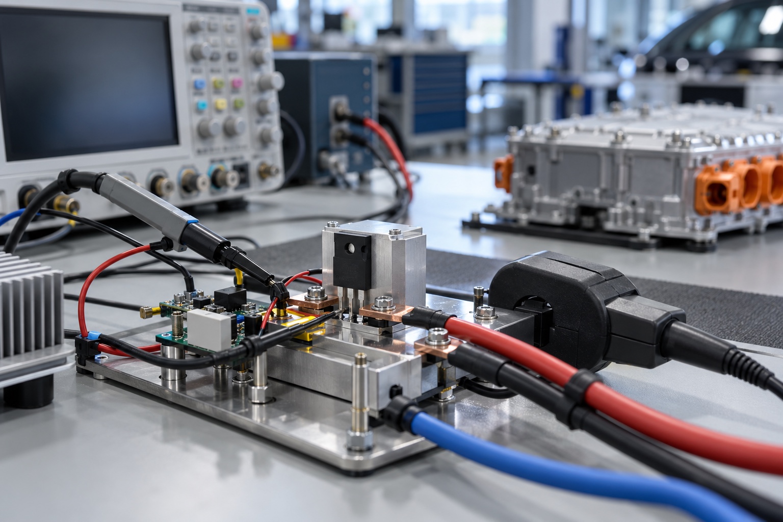
Fast switching makes loop inductance and unwanted coupling harder to ignore. Review the specific device's recommended positive and negative gate-voltage limits, drive-current needs, gate resistance, and protection requirements. Keep the gate loop compact, use a Kelvin source connection where the package provides one, and assess false turn-on during high dv/dt events. Overcurrent and short-circuit protection should be tested with the actual device and power stage rather than copied from an unrelated reference design.
Double-pulse testing is useful because it exposes switching energy, overshoot, ringing, and reverse-recovery behavior under controlled conditions. Record bus voltage, current, temperature, gate voltage, gate resistance, and test-loop inductance. These conditions are essential when comparing two devices: an Eon or Eoff number from one setup cannot be transferred unchanged to another converter.
Check What “Automotive Grade” Covers
The Neditek guide describes automotive-grade SiC MOSFETs with AEC-Q101 and HV-H3TRB qualification language and references IATF 16949 manufacturing. For procurement, request evidence tied to the complete part number and its current manufacturing configuration. Check the qualification report version, relevant wafer and package sites, temperature range, and how product changes are communicated.
AEC-Q101 is a component qualification framework. It does not, on its own, certify a complete inverter, charger, or vehicle for functional safety. Nor does it prove that a device will meet a particular vehicle's lifetime target. That judgment needs the vehicle mission profile, thermal cycling, fault strategy, and system validation.
A Workable Decision Sequence
First, set the voltage and current envelope from the application, including transients and fault conditions. Next, shortlist exact part numbers whose package and thermal path fit the assembly. Compare conduction and switching losses at relevant temperatures and waveforms, then validate the gate drive and protection on representative hardware. Finally, review part-specific qualification evidence and change-control requirements with the supplier.
This sequence keeps the decision grounded in the power stage that will use the device. It also makes conversations with Neditek more productive: a bus-voltage range, target topology, cooling method, switching frequency, and package constraints are more useful than asking for an automotive SiC MOSFET by voltage class alone.