 Neditek
High Power Amplifier RF: How To Match Specs To Your System
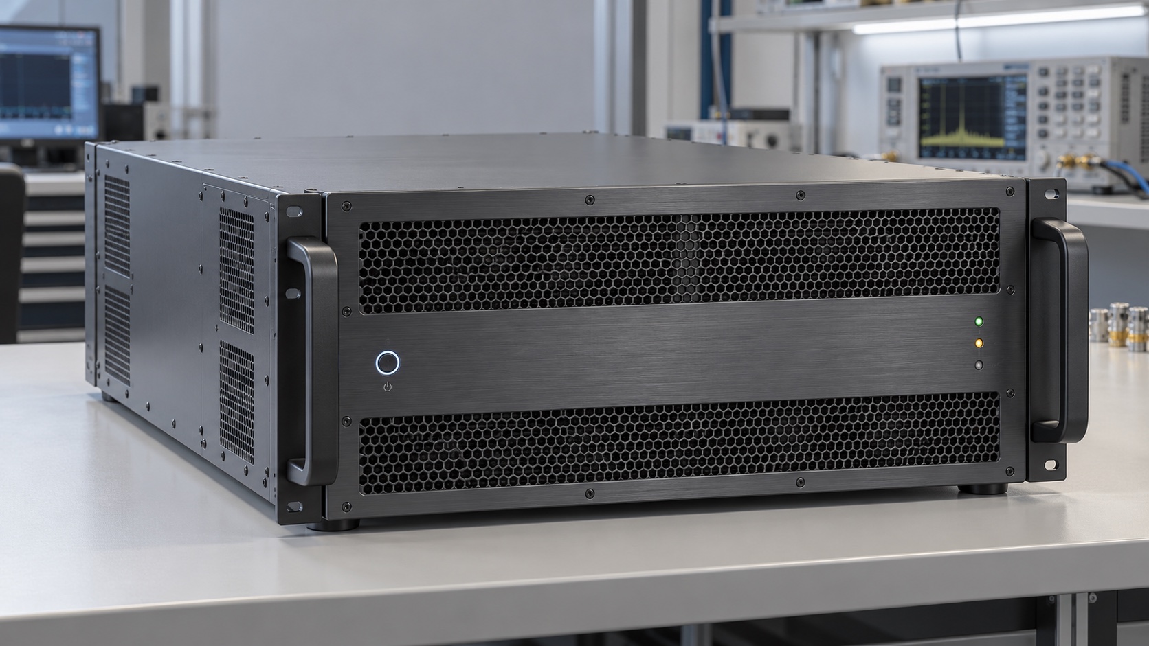
A high power amplifier rf purchase can look simple until two units with similar wattage turn out to serve very different systems. One may cover the required frequency range but miss the needed linear output. Another may meet the power target in a short pulse yet create too much heat in continuous operation. The useful starting point is therefore the signal and operating condition, followed by the amplifier specification.
Define The Job Before Comparing Watts
Write down the full operating band, required power at the system output, signal type, duty cycle, ambient conditions and load mismatch. A steady carrier, a pulsed radar signal and a modulated communications waveform can put different demands on an amplifier even when their nominal frequency is identical. There is no universal wattage threshold that makes an RF amplifier “high power”; the frequency and operating mode matter.
Decide what you need delivered. A transistor, an amplifier module and a complete solid-state power amplifier (SSPA) place different responsibilities on the system integrator. A transistor still needs matching, biasing and thermal design. A complete SSPA may incorporate driver stages, power combining, control, monitoring and cooling. Confirm which functions are included in the unit under consideration rather than assuming that every product described as an RF power amplifier has the same boundaries.
Read The Output Power Definition
The number beside “output power” needs a definition. P1dB is the output level where gain has fallen by 1 dB from its small-signal trend. Psat describes operation near saturation. A rated output is a manufacturer-stated operating value under specified conditions. These figures are not interchangeable. For a modulated signal, usable average power may need to sit below the compression or saturation level to meet error-vector magnitude and adjacent-channel requirements.
Ask for the power measurement across the intended frequency band and at the intended temperature, input drive and duty cycle. A pulse rating should include pulse width and duty cycle; neither peak pulse power nor a single-frequency result establishes continuous-wave performance across a wider band.
Neditek’s solid-state amplifier catalog illustrates why context matters. NDPM020003 is listed for 0.08–1 GHz with 100 W output power and 50 dB power gain in a 4U × 600 mm package. NDPM020025 is listed for 8–12 GHz with 400 W and 56 dB in the same stated package size. Those are catalog entries for different frequency ranges. The table alone does not establish their linear, pulsed or continuous-wave limits, so the applicable operating specification still needs to be confirmed for a project.
Check The Whole Band, Not The Center Point
For a broadband RF power amplifier, a strong center-frequency number can conceal weaker performance at a band edge. Compare the minimum gain, output power, input and output match, efficiency, spurious output and stability across the entire required range. If the application uses only a narrow sub-band, define that range precisely; if it must sweep widely, request results at enough points to expose the worst case.
Gain also affects the driver. Power gain in dB is the difference between RF output and input power expressed in dBm, but gain changes as an amplifier approaches compression. Size the driver from the operating-point gain, not just a small-signal figure. Include cable and interface losses in the drive budget.
Make Thermal And Installation Limits Explicit
Efficiency figures need the same measurement boundary. Drain efficiency compares RF output with the active device’s DC input, while power-added efficiency also accounts for RF input. Neither automatically equals the efficiency of a complete amplifier with drivers, power conversion, controls and cooling. For installation, ask how much heat the whole unit must reject in the worst operating case and what airflow or other cooling conditions the rating assumes.
Package dimensions are only the beginning of the mechanical check. Verify rack space, depth, connectors, power supply, control interface, cooling path and access for service. At high output levels, the load, cable, attenuator and connector power ratings also belong in the design review. A load mismatch can change stress on the output stage, so obtain the permitted VSWR and any associated power derating or protection behavior.
Request A Comparable Test Record
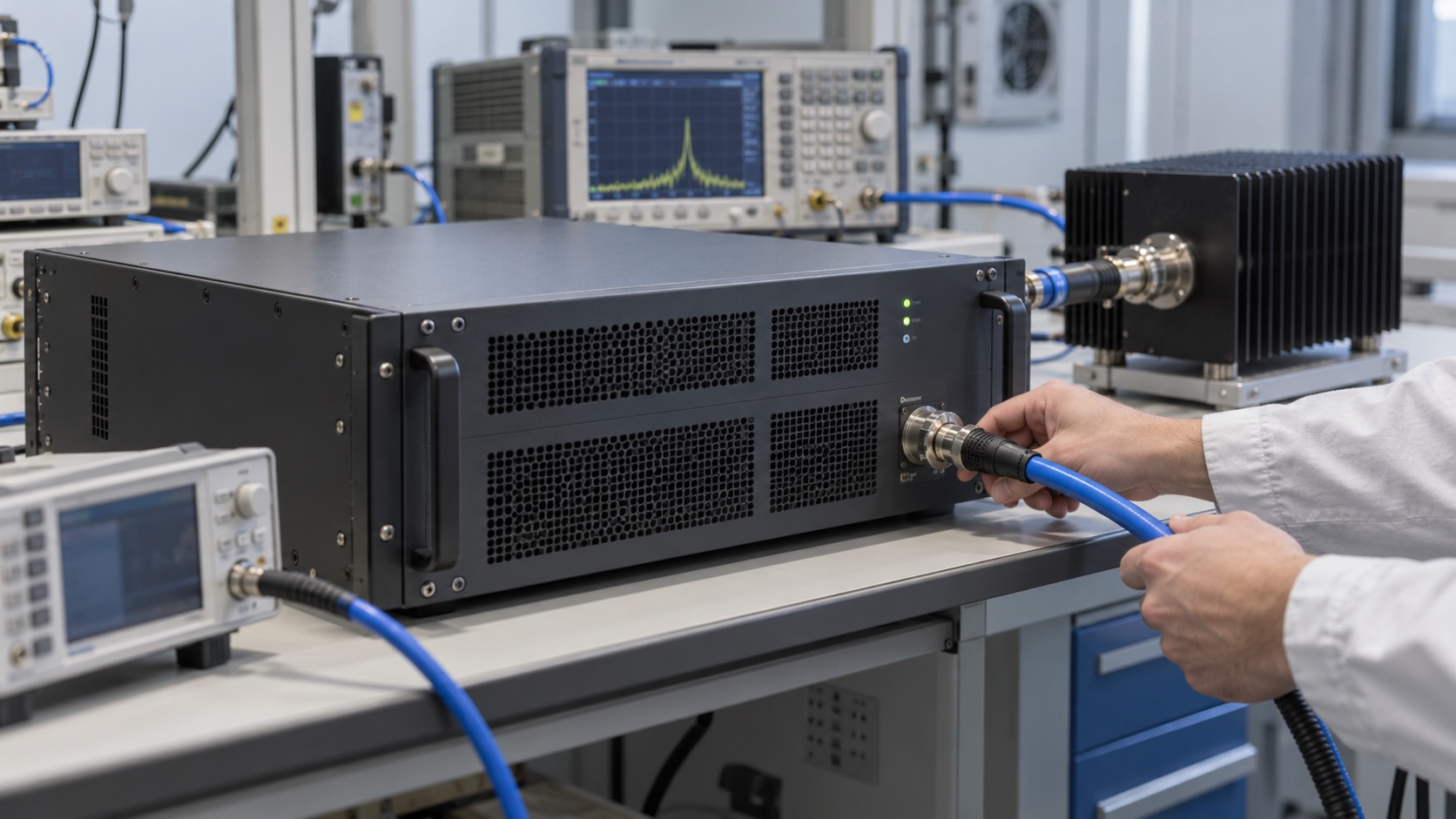
The fastest way to compare candidates is to put their data on one set of conditions: frequency points, output-power definition, CW or pulse mode, modulation, supply, temperature, cooling and load. Specify the RF measurement reference plane and account for cable, coupler and attenuator losses. Then review power, gain, linearity and unwanted emissions at the actual operating point.
For a Neditek SSPA inquiry, a practical brief is a frequency range, target power at the stated reference plane, waveform and duty cycle, acceptable linearity, available driver power, cooling arrangement and installation constraints. That gives the supplier enough context to identify a suitable product and the exact performance evidence needed before integration.