 Neditek
Broadband Low Noise Amplifier: How To Evaluate One
A receiver may need to cover several bands with one front end. A broadband low noise amplifier can simplify that architecture, but a wide frequency label alone does not tell you how the receiver will perform. The useful question is whether the amplifier maintains acceptable noise, gain, linearity and stability everywhere your system will operate, including the frequencies between the usual data-sheet spot checks.
Define The Band Before Comparing Parts
Write down the lowest and highest operating frequencies, the instantaneous bandwidth and any frequencies where strong unwanted signals may appear. A part that covers the endpoints on paper may still have a gain dip, poor input match or a higher noise figure in the middle. If a design switches among separate sub-bands, decide whether each one needs the same sensitivity and output level. That makes the comparison more useful than a single “wideband” label.
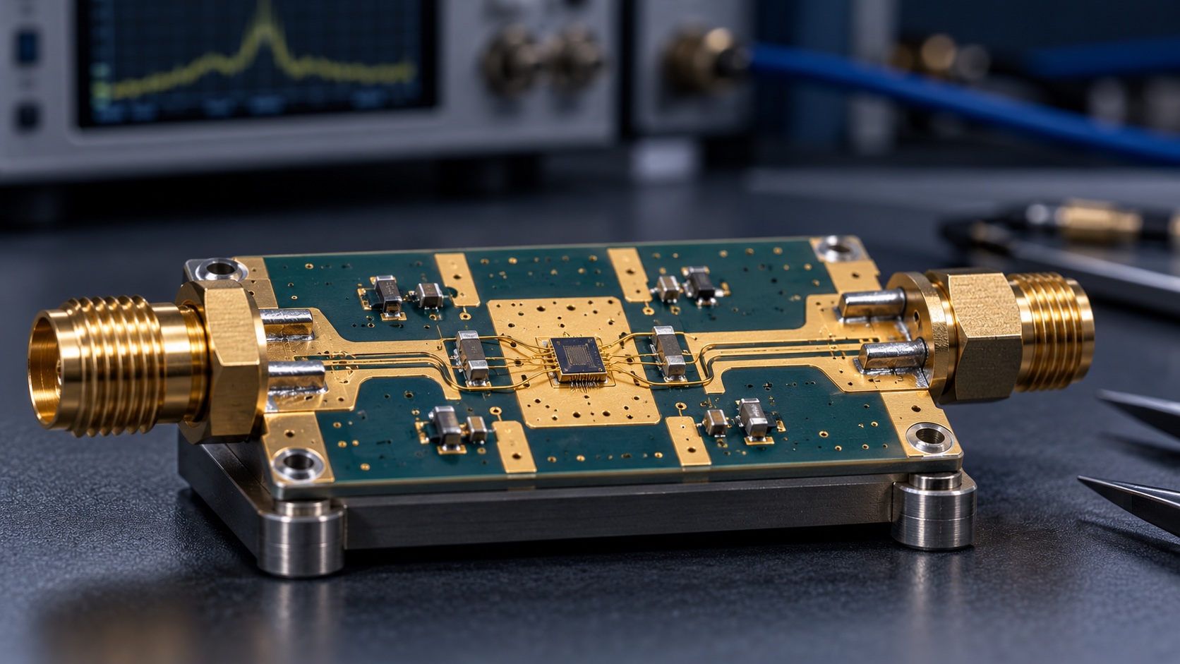
Product form matters as much as the frequency line. A bare die needs a suitable carrier, interconnect, bias network and assembly process. A packaged IC has different board and thermal requirements. Connectorized modules may include more of the surrounding circuitry, but their performance must be evaluated at the module connectors rather than assumed from a chip specification.
Read Noise Figure At The Right Reference Plane
The first gain stage has a strong influence on receiver noise. Loss in a filter, switch, limiter or feed line ahead of the amplifier raises the noise seen by the receiver before the LNA can help. Moving an LNA closer to the antenna can reduce that preceding loss, although the earlier position may expose it to stronger blockers, transmit leakage and electrical transients. Both sensitivity and input protection belong in the same design review.
For a broadband low noise amplifier, request a noise-figure curve across the required band. Check the bias voltage, temperature, source match and measurement reference plane used for that curve. A typical number at one frequency cannot be treated as a maximum across the entire band. The same distinction applies when comparing a bare die with a finished board: connectors, transitions and protection devices add losses that are absent from die-level data.
Gain Is Useful Only Within The Receiver's Range
More gain can reduce the effect of noise contributed by later receiver stages. It can also push a mixer, converter or other downstream stage toward overload when a strong signal arrives. Compare minimum and maximum gain over frequency, not just the nominal value. Gain ripple matters when the receiver must calibrate amplitude or preserve a consistent level as it tunes.
Then check linearity. P1dB describes compression under a strong signal; input or output IP3 helps assess two-tone intermodulation. Keep the input and output reference points straight when comparing these specifications. A low noise figure with inadequate blocker tolerance may produce a worse system result than a slightly noisier amplifier with more usable dynamic range.
Two Neditek Examples Show Why The Application Comes First
Neditek lists the NDAC020062 bare-die LNA with a 0.35 to 18 GHz frequency range, 1.5 dB noise figure and 17.5 dB gain in its product table. The same listing gives a 5 V supply and 80 mA current. Its broad listed span makes it a candidate to investigate for a multi-band receiver, but those summary figures do not establish the worst-case noise and gain at every frequency or after assembly.
The packaged NDGB050001 is a different option: its listed range is 0.7 to 3.8 GHz, with 0.6 dB noise figure, 22 dB gain and 34 dBm output IP3 in an 8-pin 2 × 2 mm DFN package. Those catalog values are useful screening points, not a direct ranking against the bare-die device. The frequency coverage, package, reference plane and unstated test conditions differ. Ask for the current data sheet and application guidance before turning either listing into a design limit or purchasing decision.
Check Matching, Stability And Implementation
Input and output return loss affect how well the amplifier interacts with the antenna network and the next stage. An apparent 50-ohm interface does not guarantee the same result on every PCB. Layout, grounding, decoupling, bias routing and package transitions can all change the measured response.
Stability deserves attention beyond the intended receive band. Source and load impedances vary with switches, filters, cables and temperature; a circuit that looks well behaved at one test frequency can show unexpected gain peaks or oscillation elsewhere. Review full-frequency S-parameters and the expected source and load conditions. For a bare die, include bond wires and carrier transitions in the model. For a packaged part, start with the recommended evaluation layout and verify the finished board.
Test The Complete Signal Path
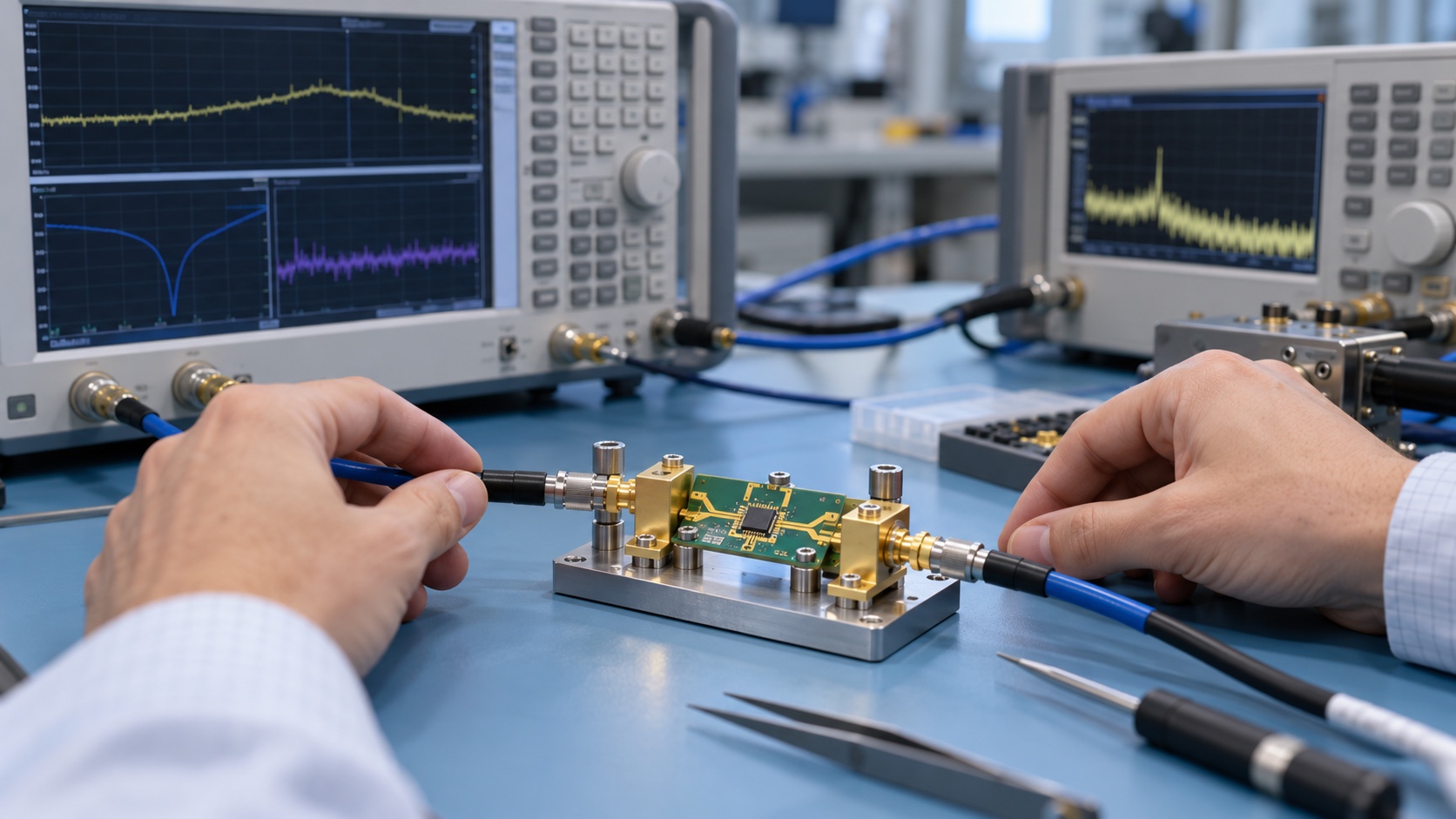
Before noise testing, confirm the supply current and sweep the small-signal response to catch wiring, bias or stability problems. Measure gain, matching and noise figure across the whole operating band using the same bias and temperature conditions. Add compression and two-tone tests at the frequencies and signal levels that matter to the receiver. Extend stability checks into relevant out-of-band regions, especially when the input network can change state.
Define the measurement plane explicitly. A result measured at the die pads is not interchangeable with one measured at board connectors. If a filter or limiter precedes the amplifier, measure or budget its loss and verify that its protection behavior still leaves a safe input level for the LNA. Finally, repeat the checks in the expected environmental and assembly conditions. That is how a promising broadband component becomes a dependable receiver front end.
What To Request Before Selection
For each candidate, collect full-band noise and gain data, return loss or S-parameters, P1dB, IP3, supply requirements, package or die-assembly guidance, temperature limits and product status. Mark each value as typical, guaranteed or measured in your own setup. If a required curve or test condition is missing, treat it as a question to resolve with a sample and an evaluation board. The best broadband low noise amplifier is the one whose verified behavior fits the entire signal chain, not the one with the widest range printed in a table.