 Neditek
What Are Schottky Diodes? Uses, Types And Selection
A diode on a microwave detector board and one in a power converter may both be called a Schottky diode, yet they solve very different problems. The detector needs to respond to a small, fast signal. The converter needs to carry current while staying within its voltage and thermal limits. Understanding the shared operating principle is useful; choosing a part still starts with the circuit it must serve.
What Makes A Diode “Schottky”?
Schottky diodes use a metal–semiconductor contact to form the barrier that controls current. Current flows readily in the forward direction once the applied voltage is sufficient for that particular device and operating condition. Compared with a conventional PN-junction diode, a Schottky device generally has a lower forward voltage and does not rely on stored minority carriers for conduction. That lack of minority-carrier storage helps it respond quickly when the signal changes.
Those traits are useful, but they do not make every Schottky diode interchangeable. Reverse leakage, reverse-voltage capability, junction capacitance, series resistance and temperature behavior depend on the material and device structure. Even the forward voltage is meaningful only with its stated test current and temperature. A value from one data sheet should not be treated as a universal “turn-on voltage.”
Why Are Schottky Diodes Used In RF Circuits?
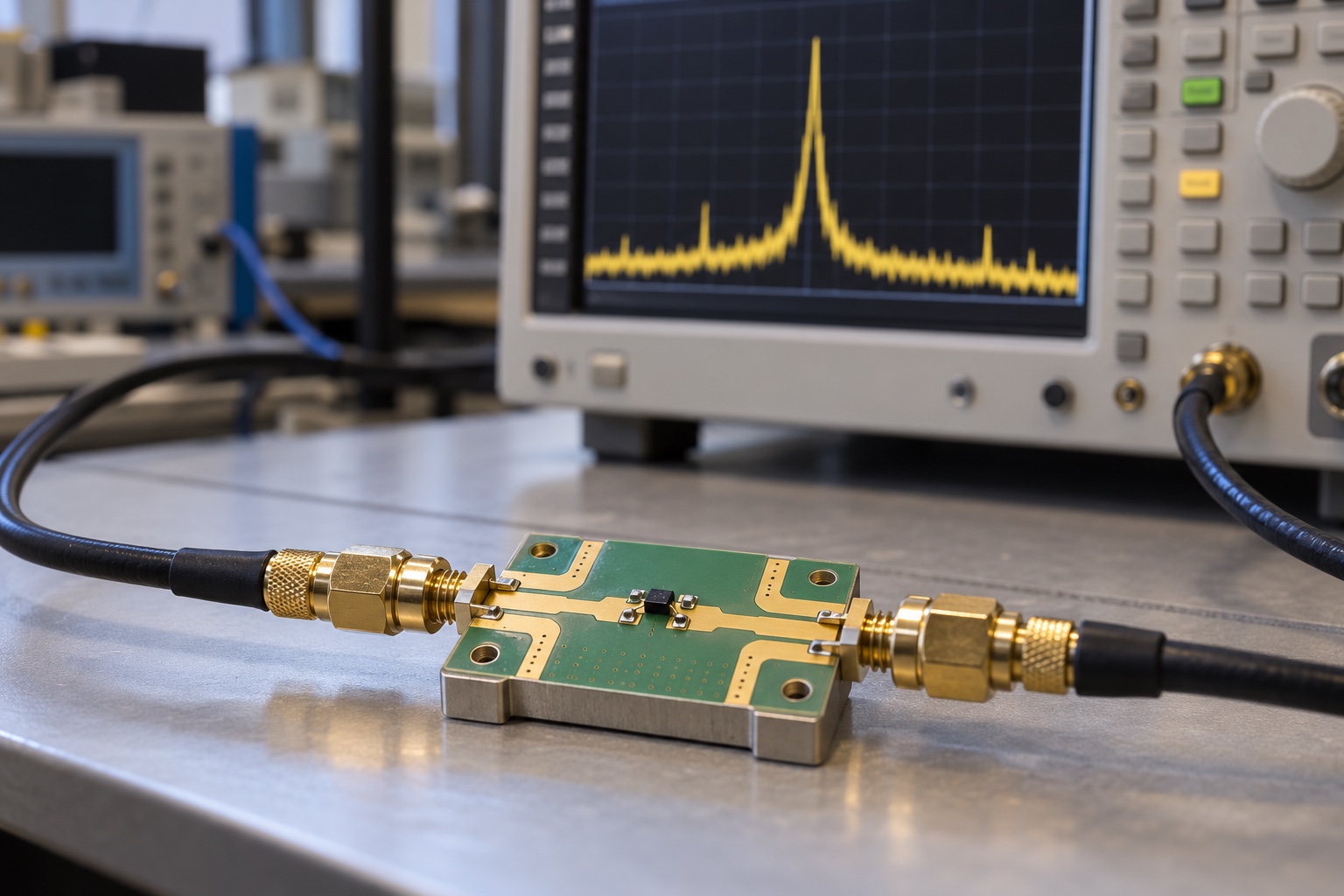
The current–voltage relationship of a Schottky junction is nonlinear. In a detector, that nonlinearity lets a circuit turn an RF input into a lower-frequency output that can be measured or processed. In a mixer, a local oscillator drives the diode so the output contains combinations of the RF and oscillator frequencies. Filtering and the rest of the circuit determine which frequency component is useful.
This explains why a diode chosen for detection may differ from one chosen for mixing. For a weak-signal detector, sensitivity at the intended frequency and input level matters. For a mixer, the designer also needs to consider local-oscillator drive, conversion performance and the chosen circuit topology. Junction capacitance and series resistance affect high-frequency behavior, while the package and interconnect add their own parasitic effects.
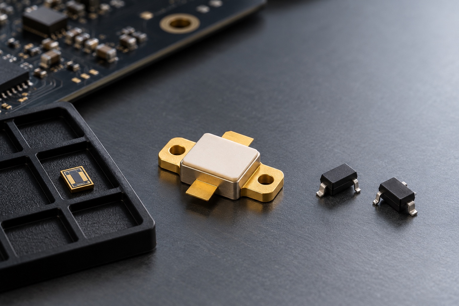
Neditek’s RF Schottky range illustrates the variety. Its product information lists silicon detector and mixer chips, metal-ceramic packaged devices, beam-lead chips and surface-mount diode pairs. These are different implementation options, not a single part offered in several interchangeable housings. A bare die may suit a tightly controlled microwave assembly; a packaged device may simplify handling and board integration. The correct comparison is between complete part numbers under comparable test conditions.
What About Power Schottky Diodes?
In a power circuit, the same barrier principle is used for rectification rather than small-signal detection. The selection questions change accordingly: How much reverse voltage must the diode withstand? What average and surge currents will it see? What forward loss and junction temperature will result in the actual thermal design? Neditek’s product catalog separates silicon power Schottky devices and SiC Schottky barrier diodes from its RF detector and mixer families.
That separation matters. A tiny RF detector die cannot be selected by the criteria used for a power rectifier, and a power rectifier cannot be assumed to work well at microwave frequencies simply because both are Schottky devices. The first may be specified by capacitance, series resistance and voltage sensitivity. The second is judged mainly against voltage, current, forward drop, surge and heat limits. Material and package choices should follow those requirements.
How To Choose The Right Device
Begin with the job in the circuit: detection, mixing or power rectification. Then write down the operating frequency or switching conditions, expected signal or load level, reverse-voltage stress and temperature range. This keeps a promising-looking forward-voltage number from hiding a more important limit.
For RF detection, compare sensitivity at the frequency, input power and bias conditions that resemble your design. For mixing, check the available local-oscillator drive and the performance conditions used for the published figures. Review capacitance, resistance, barrier type and packaging together. If the design uses a dual diode, check its internal connection and pinout. Similar-looking three-pin packages can contain different diode arrangements.
For power rectification, compare reverse-voltage rating, average and surge current, forward voltage at a stated current, leakage and thermal limits. A useful final check is to confirm that the proposed part remains within its limits at the board’s highest expected temperature and during transients, not just under a room-temperature bench test.
The Practical Takeaway
So, what are schottky diodes? They are metal–semiconductor barrier diodes valued for fast response and useful forward conduction characteristics. In RF systems, their nonlinearity makes detection and mixing possible. In power systems, they are selected for rectification under specific electrical and thermal conditions. Start with the application, read the test conditions behind each specification, and compare devices within the right product family.