 Neditek
How To Check Schottky Diode Operation With A Multimeter
A receiver stops detecting weak signals, and a tiny diode on the RF board becomes the first suspect. A multimeter can help you find a shorted or open junction, but the result needs context. Before touching the probes, identify the part and its internal connections. That matters especially with three-pin Schottky diode pairs, where the same package shape can hide different arrangements.
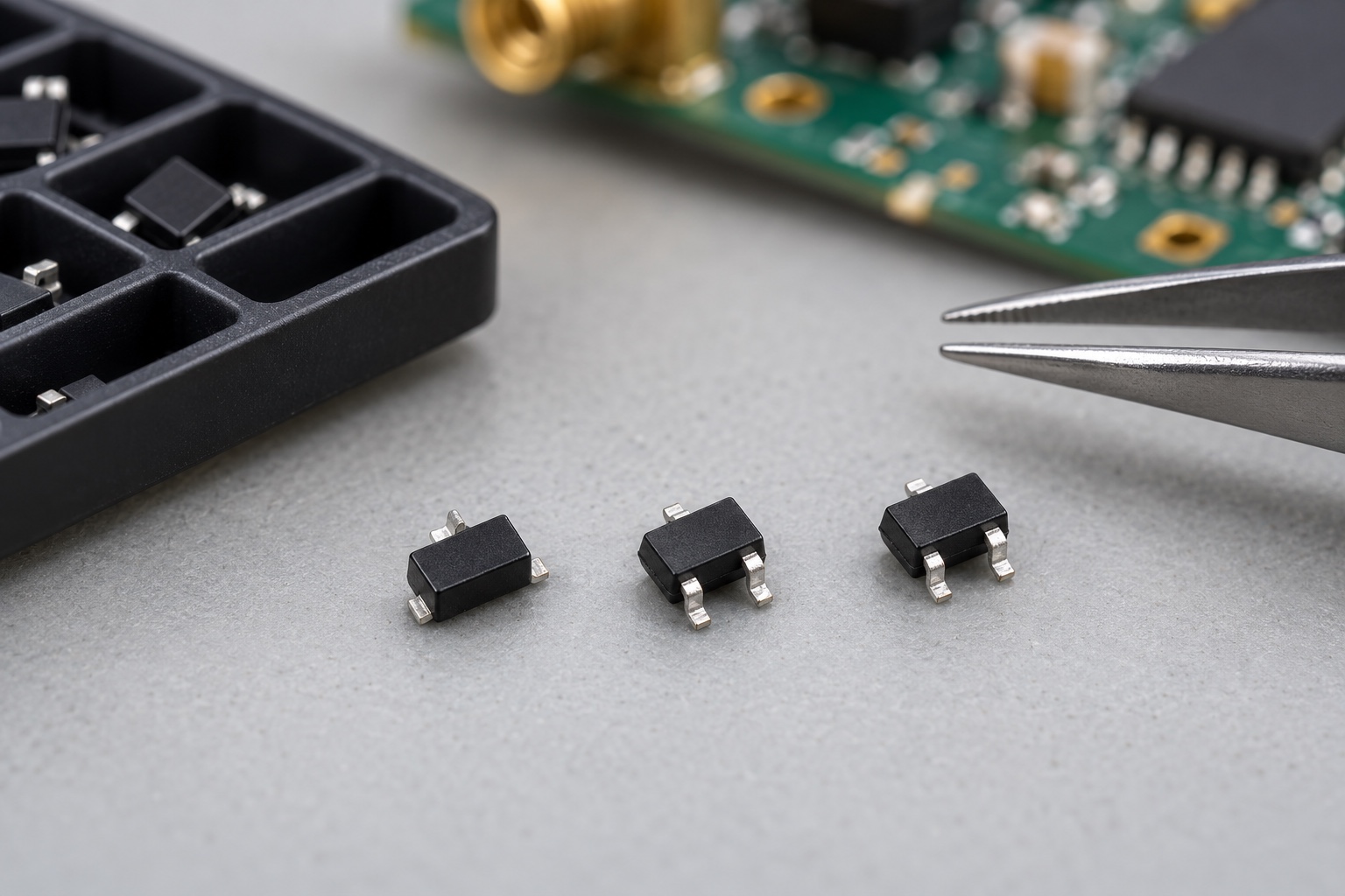
What To Prepare Before Testing
Turn off the equipment, disconnect its power source, and discharge stored energy according to the equipment's service procedure. If the diode is still mounted, nearby resistors, capacitors, protection networks, or other semiconductor junctions can create misleading readings. For a reliable check, test the part out of circuit, or isolate a lead using an appropriate repair process.
Find the full part number and pin diagram before measuring. A two-terminal diode has one anode and one cathode. A three-terminal package may contain a common-anode pair, a common-cathode pair, a series pair, or even a single diode with another pin serving a different purpose. Package size and pin count alone cannot tell you which one you have.
Use the meter's diode-test setting. The reading in this mode reflects the voltage across the junction at the meter's own test current, so it is useful for comparison with a datasheet condition but is not a universal pass value. Handle small RF devices with suitable ESD precautions and avoid forcing the probes onto fragile leads.
How To Check A Two-Terminal Schottky Diode
Place the red probe on the anode and the black probe on the cathode. A conducting junction should give a forward reading. Reverse the probes: the meter should normally show no conduction within its diode-test range. Record both results rather than relying on one number.
If the meter shows conduction in both directions, suspect a short or an alternate path through the board. If it shows no conduction in either direction, suspect an open device, poor probe contact, or a meter whose test voltage and range are unsuitable for that particular part. Repeat the measurement with the device isolated before deciding that it has failed.
Avoid the tempting rule that every Schottky diode must read the same forward voltage. Neditek's RF detector diode data, for example, specify forward voltage at a stated 1 mA test current and distinguish between typical and maximum values. The meter's test current may differ. Compare a measured value with the correct part's datasheet, under comparable conditions, rather than a generic figure seen elsewhere.
How To Check A Three-Pin Schottky Diode Pair
Write down the three possible pin pairs: 1–2, 1–3, and 2–3. Test each pair twice, once with the probes in each direction. The six readings form a simple map of where a junction conducts and where it blocks. Then compare that map with the internal connection diagram for the exact part number.
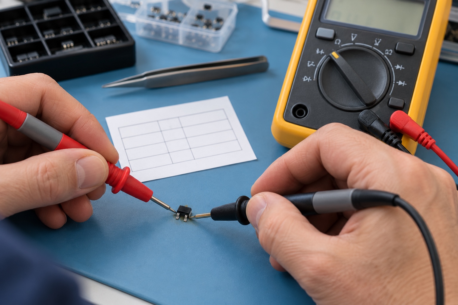
For a common-cathode pair, two anodes share one cathode; a common-anode pair reverses that arrangement. A series pair has a different path through its middle connection. These patterns are helpful only when checked against the actual pin diagram. A three-pin package that looks identical to another part is not proof that the two devices can be substituted.
Neditek lists surface-mount Schottky detector diodes and Schottky diode pairs among its RF products, including compact SC-79 and SOT-323 package options. The right comparison therefore starts with the exact package, part number, and internal topology, followed by the electrical specifications relevant to the circuit.
What A Multimeter Result Can And Cannot Tell You
The diode-test setting is a first check for polarity, open circuits, and obvious shorts. An unexpected result on the board is a reason to isolate the device and retest, not an immediate verdict on the component.
A normal forward and reverse reading does not establish that an RF detector or mixer diode will work at its intended frequency. Junction capacitance, series resistance, matching, package parasitics, and temperature behavior require measurements under defined conditions. The same meter check also cannot prove reverse breakdown voltage or power handling; those tests need appropriate current limiting, safety measures, and acceptance criteria.
If the diode passes the basic check but the circuit still fails, return to the function it performs. In an RF detector, compare the part's capacitance, series resistance, sensitivity, and specified operating conditions with the design. For a diode pair, verify both junctions and their topology. This keeps a quick bench check in its proper role: a useful starting point, followed by the measurements that actually determine whether the part suits the circuit.