 Neditek
How Does an RF Mixer Work and What Are the Main Types?
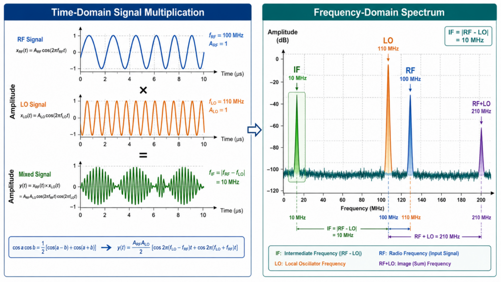
A radio frequency mixer (RF Mixer) is essentially a nonlinear device with three ports (RF, local oscillator LO, and intermediate frequency IF). It multiplies two signals in the time domain to achieve frequency conversion, and the new frequency output is just the sum and difference of the original input frequencies. Many engineers can easily recite the basic formula:fif=fRF±fLOfIF =fRF ±fLO
However, in actual system design, once a leakage wave from the LO end to the RF end causes the sensitivity of the entire receiving link to decrease, or the third-order cross-tuning product (IMD3) directly drowns out the adjacent weak signal, the rote formula alone will blind you. To truly master this, we must set aside textbook stereotypes and dissect the underlying physical nonlinear mechanisms that drive these devices. This article will help you clarify how the IV characteristic curve causes frequency conversion, and provide a selection framework based on actual data to help you make the most correct choice in single-balance, double-balance or even triple-balance topologies according to the strict dynamic range requirements.
The Underlying Physics: How Exactly Do RF Mixers Work?
Core mechanism: multiplication in the time domain
Remember this: nonlinearity creates new frequencies. When a radio frequency (RF) signal and a high-power local oscillator (LO) signal pass through the nonlinear IV curve of the diode at the same time, the device becomes a “mathematical multiplier”.
Linear systems cannot be mixed. If you add two signals to an ordinary linear resistor, it is just a simple superposition of voltages, and the frequencies of the two are still independent of each other and do not interfere with each other. To achieve two distinct peaks in the spectrum, f1+f2f1 +f2 and f1−f2f1 −f2, one must rely on the square-law characteristics of components such as Schottky diodes or field-effect tubes (FETs).
The role played by Ben Zhen (LO)
You can use LO as a high-speed electronic switch. In a standard passive diode ring mixer, the LO signal must be strong enough (usually between +7 dBm and +17 dBm) to push the diode hard into the forward biased (fully on) and reverse biased (completely off) states.
If the LO drive power is not given enough, the diode will get stuck in the awkward linear transition zone. This not only causes the mixer to lose its switching ability, but also causes the conversion loss (Conversion Loss) to deteriorate sharply, directly destroying the noise figure of the entire system. In turn, if the LO power is pushed too hard, it will excite severe high-order harmonics. Once these harmonics leak into the intermediate frequency (IF) port, you will have to add extremely expensive and aggressive filters behind the mixer to clean up the mess.
“3-I” Rule For Mixer Selection
When many engineers choose mixers, they habitually only look at whether the frequency band is correct. But in real RF link design, what you really need to look at is the “3-I” selection matrix: impedance (Impedance), isolation (Isolation), and intersection (Intermodulation).
Impedance (Impedance) —— Standing Wave Ratio Limitation: It is almost impossible for a broadband mixer to achieve a perfect 50 ohm match between three ports simultaneously. It is common practice to add an attenuation network (Pad) to hard-core a broadband match.
Isolation (Isolation) —— leakage wave problem between ports: The strength of LO signal is several orders of magnitude higher than that of RF signal. If the isolation from LO to RF is too poor, the LO signal will leak out in the reverse direction along the antenna, which will most likely cause your product to be directly planted on the FCC radiation standard.
Intermodulation (IP3 performance): The higher the input third-order Intermodulation Intercept Point (IIP3), the stronger the receiver’s ability to survive in crowded and noisy RF environments, and the less likely it is to generate ghostly false signals.
| 3-I Metric | Design Priority Level | Component Impact |
| Impedance (VSWR Constraints) | High (Broadband Matching) | Requires the addition of attenuator pads at mixer ports to force a 50-ohm match, which reduces overall system gain. |
| Isolation (Port-to-Port Leakage) | Critical (Regulatory Compliance) | Dictates tighter front-end filter requirements and sizing to prevent strong LO signals from leaking backward out the antenna and violating FCC emission limits. |
| Intermodulation (IP3 Performance) | Critical (Interference Immunity) | Drives the linearity requirements for the LNA and mixer; insufficient IIP3 results in the generation of false phantom signals in crowded RF environments. |
What Are The Main Stream RF Mixers?
Active Mixer vs Passive Mixer
Passive mixers are inherently subject to variable frequency loss, which is generally between 6dB and 8dB. They mainly rely on Schottky diodes or passive FET switches to operate, and do not require DC bias voltage at all. The advantages are excellent linearity and extremely low phase noise, so high-end test instruments basically choose it by default.
Active mixers provide variable frequency gain through an internally integrated transistor stage (most commonly the Gilbert cell architecture), but this thing must have a continuous DC power supply. While the built-in gain allows you to eliminate the amplifier stage that follows the mixer, the transistor’s own noise floor can make the overall noise figure significantly worse than that of passive solutions.
Single-balance, double-balance, and triple-balance mixers
The degree of “balance” of the mixer determines how deeply it counteracts overlapping frequencies and suppresses useless spurious emissions.
Single balanced mixer: consists of two diodes and a Barron transformer. It can isolate LO and RF ports, but will allow the LO signal to run directly to the IF port. It is generally only chosen if the budget is stuck and a readily available narrowband IF filter is available later.
Double balanced mixers (DBM): This is the absolute workhorse of the industry. It uses a four-diode ring structure and has a balun installed on both the RF and LO ports. This symmetrical design can suppress the RF and LO carriers at the IF output terminal at the same time, and can also eliminate all even-order cross-tuning products.
Triple-balanced mixer (double-double balanced): Two sets of completely independent diode rings are used, and all three ports are equipped with overlapping baluns. The bandwidth is surprisingly wide, even allowing IF and RF frequencies to overlap. The disadvantages are that it is extremely expensive to consume LO drive power (+19 dBm or even higher at every turn) and is very expensive.
A Pit That Even Veterans Will Step On: The Impedance Trap Of The IF Port
Staring at the IP3 indicators on the data manual will often give you a false sense of security. You know, the manufacturer measured these data in a perfectly matched 50 ohm environment in the laboratory.
However, at the actual PCB artboard stage, the IF port is usually directly connected to an intermediate frequency filter that exhibits high reactance characteristics. This mismatch at the IF end will reflect our unwanted sum-frequency signal (fRF+fLOfRF +fLO) back into the diode ring unchanged.
Real case analysis:
When we were developing a Sub-6GHz small base station receiver, the team used an off-the-shelf double-balanced mixer with a nominal IIP3 of up to +25 dBm. We cascaded it directly into an acoustic surface wave (SAW) filter, and the measured IIP3 dropped directly to +19 dBm. After catching the insects, it was found that the out-of-band reactance impedance of the filter completely reflected the sum-frequency product back. Later, we strung a simple 3dB resistive attenuation network (which would also work with a duplexer) between the mixer and the filter to absorb the reflection. Although the total gain of 3dB was sacrificed, IIP3 successfully recovered to +24 dBm.
Remember one iron rule: always make sure that all ports of the mixer have good resistive terminations in the wideband range.
Industry Frontier Trends: SOI Technology In Millimeter Wave
In the past, high-frequency mixers were almost entirely dominated by gallium arsenide (GaAs) pHEMT technology. But as the current industry evolves towards 5G millimeter wave (mmWave) systems, everyone is turning to silicon-on-insulator (SOI) processes. The SOI process is quite hard-core. It can not only fully integrate the mixer, LO multiplier and IF amplifier into the same monolithic chip, but also maintain the high isolation previously achieved only by GaAs discrete devices.
Frequently Asked Questions (FAQ)
What is the difference between an RF mixer and a modulator?
The task of a mixer is to move a signal from one frequency to another, but it never changes the underlying information contained in the signal. A modulator, on the other hand, changes the amplitude, phase, or frequency of a bare carrier wave to “burn” baseband data (such as speech, video, or digital bitstream onto the waveform.
Why does passive mixer require such high LO drive power?
Because passive mixers use diodes as hard switches. A high enough LO drive voltage can force the diode to switch extremely quickly between the “full on” and “full insulated” states. If LO is too weak, the diode will not move in the linear region, the multiplication effect will disappear, and then there will be catastrophic signal attenuation.
Can RF mixers be used as phase detectors?
Absolutely. As long as two signals of the same frequency are fed to the RF and LO ports respectively, the mixer will spit out a direct current (DC) voltage at the IF port. The magnitude of this DC voltage is proportional to the phase difference between the two input signals ——this is also the core mechanism by which the phase-locked loop (PLL) can work properly.
What does the mixer’s 1dB compression point (P1dB) mean?
P1 dB refers to the corresponding RF input power level when the frequency conversion loss of the mixer increases by 1 dB from the theoretical value when it is linear. If the RF power crosses this red line, the mixer will enter saturation, which will not only cause serious signal distortion, but also extremely bad cross-tuning interference.
How to measure the isolation from LO to RF?
Operation is not difficult: first terminate the IF port with a precise 50 ohm load. Then a LO signal of known power (say +10 dBm) is injected into the LO port. Next, connect the spectrometer to the RF port to measure the power value of the peak at the LO frequency. The difference between the injected power and the measured power (in dB) is the isolation you want.