 Neditek
What Is RF Filter? Top 7 RF Filter Types You Must Know
Radio frequency (RF) filters, to put it bluntly, are 1 passive devices that are designed to control the spectrum-allowing specific signals to pass smoothly (the lower the insertion loss, the better), while blocking unwanted out-of-band frequencies. Whether the receiver sensitivity of the communication system is OK or not and whether the transmitter can be out of regulation are all up to it. If you choose the wrong filter, your analog-to-digital converter (ADC) will definitely saturate, and the FCC’s launch test will definitely not pass. In this article, let’s not talk about the textbook definition that is universally applicable. From the perspective of hardware engineers, we can see how to choose the seven most mainstream RF filters in the industry under the real trade-off model.
Engineering Truth: What is a RF Filter?
In the entire RF link, the filter is a “spectral gatekeeper”. Its core task is to help you seize the “spectrum territory” in a dense electromagnetic environment “. Engineers don’t think of it as a perfect mathematical model at all. Instead, they think it is a “headache but something to use”. After all, any filter introduces insertion loss (wasting valuable RF power) and phase distortion. So the real engineering challenge is that you have to pick a topology with a roll-off that is steep enough to keep the adjacent channel interference stuck out without ruining the desired signal.

“SQC Trade-off Triangle”: A Selection Framework for Hardware Veterans
Choosing a filter is essentially an extremely cruel compromise between volume (Size), Q value (Q-Factor) and cost (Cost). You can only account for two of these 3. I call it the “SQC trade-off triangle”.
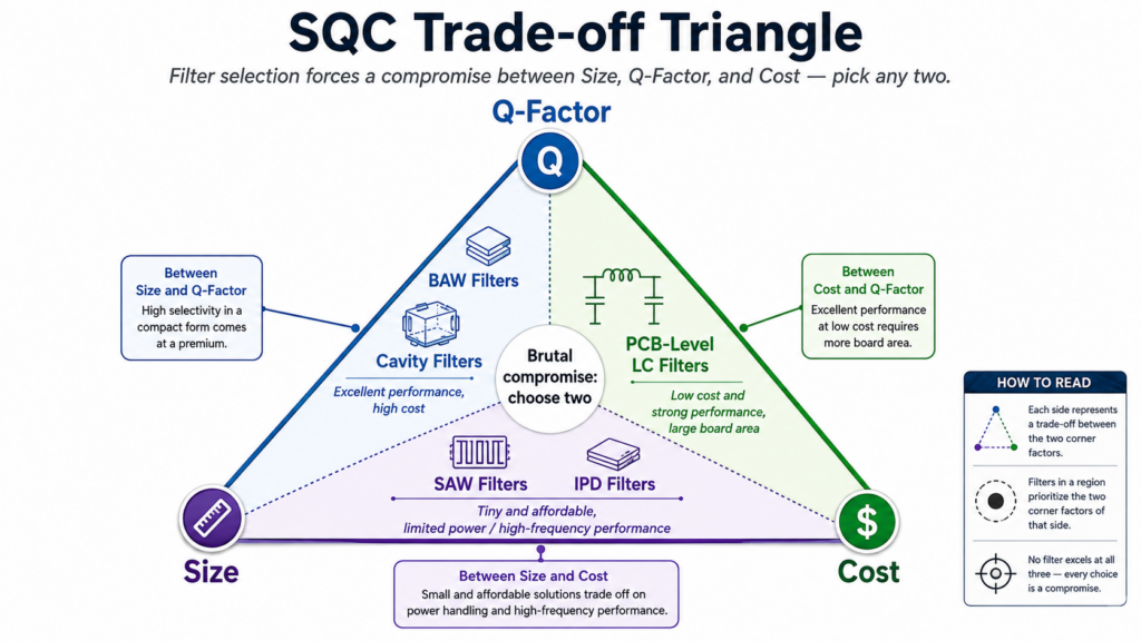
A high Q value (quality factor) means that the edge of the cut-off frequency is sharp and the insertion loss is low. However, if you have to make the volume small, the Q value will usually be greatly reduced. However, if you want to reduce the BOM cost, you can only use some cheap materials. As a result, 1 you encounter temperature changes, the performance will easily float.
Size Q: You can get BAW or cavity filter. Performance is not a choice, but the unit price is really expensive.
Size cost: This corresponds to a common SAW or IPD filter. They are extremely small and cheap, but 1 stop when it comes to high-power processing and high-frequency scenes.
Cost Q value: The final result is the kind of PCB-level LC filter that occupies the place. Cheap, performance is also good, the price is extremely waste of space on the board.
7 types of RF filters that must be understood
Hardware engineers typically classify them by physical structure and acoustic/electromagnetic properties. The following seven technologies have basically dominated the development of modern RF systems.
Top 7 RF Filter Types: Comparison Table
| Filter Type | Frequency Range | Q-Factor Level | Relative Cost | Best Application |
| BAW (Bulk Acoustic Wave) | 1.5 GHz – 7 GHz | High | High | 4G/5G smartphones and high-frequency Wi-Fi requiring extreme performance in a small footprint. |
| Cavity Filters | 30 MHz – 40+ GHz | Very High | High | Telecom base stations, radar, and aerospace systems demanding massive power handling. |
| SAW (Surface Acoustic Wave) | 50 MHz – 2.5 GHz | Moderate | Low | GPS, legacy mobile bands, and low-cost IoT devices operating at lower frequencies. |
| IPD (Integrated Passive Device) | Wideband (Up to 10+ GHz) | Low to Moderate | Low | Highly miniaturized wearables, RF modules, and IoT devices where space and price are strict. |
| PCB-Level LC Filters | DC – 3 GHz | High | Very Low | Broad custom RF prototyping and systems where board space is abundant. |
| Ceramic Resonator Filters | 500 MHz – 8 GHz | High | Medium | 5G small cells, massive MIMO systems, and medium-power infrastructure. |
| LTCC (Low-Temp Co-fired Ceramic) | 1 GHz – 40+ GHz | Moderate | Low to Medium | Compact RF front-end modules, mmWave applications, and integrated Bluetooth/Wi-Fi packages. |
SAW (Surface Acoustic Wave) Filter: Standard Configuration Below 2GHz
In consumer electronics products below 2GHz, SAW filters are definitely dominant, after all, their size-to-cost ratio is too invincible. It works by converting electrical signals into surface acoustic waves using piezoelectric materials (such as lithium tantalate). It is suitable to do traditional GPS, 2G/3G and early 4G frequency bands. However, once the frequency exceeds 2.5GHz, its physical bottleneck will come out-the finger spacing of the interdigital transducer (IDT) is extremely small, it is difficult to mass produce reliably, and the insertion loss will be ridiculously high if it is hard to do so.
BAW (Bulk Acoustic Wave) Filter: Main Force Of High Frequency 5G
Where SAW can’t handle it is the time for BAW to appear, especially the spectrum from 2GHz to 6GHz. Unlike surface waves, BAW sound waves pass vertically through the entire piezoelectric material. This structure can not only resist a lot of power, but also make an extremely steep roll-off edge. Today’s 5G Sub-6GHz phones and Wi-Fi 6E/7 routers all count on BAW (and its variant FBAR) to disassemble the frequency bands that are very close to each other without crosstalk.
LC (Inductance Capacitance) Filter: PCB Level Of The Classic
If your board space tube is enough, but also to do low-frequency, high-power custom circuit, LC filter is still the most pragmatic choice. The design is very flexible with discrete patch capacitors and inductors. You can even change the capacitor directly on the test bench and adjust the center frequency on the spot. However, compared with the acoustic filter, its Q value is low, so the kind of mobile devices that require extremely strict band-pass indicators, it is not competent.
Cavity Filter: Big Mac In High-Power Base Station
The cavity filter can resist hundreds of watts of radio frequency power, even without burning. It is generally made of excellent conductive metal shell, which is inserted into the tuning rod. The Q value of this thing is frighteningly high (often breaking ten thousand), and the insertion loss is almost zero. They are usually the ones hanging from the tower of the macro base station. Of course, it’s impossible for any mobile device or consumer product to use it for its dead weight and huge size.
Ceramic Filter: A Compromise Massive MIMO
The ceramic dielectric filter is right on the pain point of the 5G massive MIMO base station on the structure. It uses high dielectric constant ceramic materials to replace the bulky metal cavity, while maintaining a good power capacity, the volume of nearly 70% cut. With it, telecom equipment manufacturers can force 64 transmit channels and 64 receive channels into a relatively mobile radio frequency antenna unit.
MMIC Filters: The Frontier Of Deep Space And Radar
Monolithic microwave integrated circuit (MMIC) filters are designed to deal with extreme millimeter-wave frequencies (usually above 30GHz). They are directly engraved on a gallium arsenide (GaAs) or gallium nitride (GaN) substrate, together with amplifiers and mixers. Not only the size belongs to the microscopic level, high-frequency stability is also excellent, aerospace systems and vehicle radar arrays can not do without it.
IPD (Integrated Passive Device) Filters: The Limits Of Miniaturization
In the field of wearable devices and IoT modules, IPD filters represent the forefront of miniaturization. It uses wafer-level semiconductor manufacturing processes (such as glass or silicon substrates) to print high-density capacitors and inductors directly, perfectly replacing discrete LC circuits. Although its roll-off is not as steep as BAW’s, it has excellent consistency in applications such as Bluetooth and Zigbee, and there is no need to worry about assembly tolerances at all.
History of Blood and Tears in Hardware Stamping Pits: 3 Pits Most Easily Falling into by Cainiao
The book teaches filter theory, and only a burned board will teach you what hardware reality is. Here are the 3 fatal mistakes novice engineers are most likely to make when selecting a model.
Pit 1: Credulous Specifications On The “Typical Value”
Many engineers are used to looking at the “typical” insertion loss at 25°C in the specification, and then use this as a benchmark to calculate the entire link budget. But the reality is that the performance of the filter at the edge of the band will be degraded. Remember, be sure to use the “Worst-case” insertion loss in the whole working temperature range to make system design, otherwise the product will definitely have a signal dead angle in the outfield.
Pit 2: Ignore TCF (Temperature Coefficient Of Frequency)
Temperature drift is the absolute killer of narrow bandpass design. As soon as an ordinary SAW filter heats up, the center frequency will drop. Originally, the signal was well isolated at room temperature. When the machine 1 ran to 85°C, the frequency response curve drifted away, directly attenuating your useful signal. If your product is to be used outdoors, remember to specify the TC-SAW (temperature compensated SAW).
Pit 3: Fake Impedance Matching
The RF filter will only work as written in the specification if the termination impedance is perfectly matched (usually 50 ohms). The PCB trace is too bad, or the shield is too close to the filter to introduce parasitic capacitance, will destroy the match. This mismatch will shift the frequency response of the filter, resulting in a larger return loss and inexplicable signal reflection.
Lab Case: Fix Wi-Fi Coexistence with LTE Band 41
How critical is it to choose the right filter? Real data from the lab best illustrates the problem. Two years ago, we tuned a smart home gateway. As long as the cellular module sends an LTE Band 41 signal, the 2.4GHz Wi-Fi connection will definitely be disconnected.
This board initially in order to save money, with a 1 ordinary SAW filter. The LTE Band 41 (up to 2690 MHz) is too close to the Wi-Fi Channel 1 (starting at 2401 MHz). The roll-off of the SAW filter was too “meat” (not steep enough), causing the 27dBm cellular transmit signal to leak directly, saturating the LNA (low noise amplifier) at the Wi-Fi receiving end.
Later, we directly replaced SAW with a 1 FBAR(BAW) filter with a high Q value. This FBAR provides up to 55dB out-of-band rejection, with the transition zone falling almost vertically. After replacing it, the Wi-Fi receiver immediately restored the bottom noise sensitivity of-92dBm, the board remained intact and the layout was not changed, and the coexistence problem was completely solved.
Frequently Asked Questions (PAA)
How To Choose BAW And SAW Filter?
If it is an application below 2GHz, and the cost and volume requirements are strict, select SAW. If it’s 2GHz to 6GHz, or you need a very steep roll-off to separate closely spaced bands (e. g., to solve the coexistence problem of Wi-Fi and 5G cellular networks), then you have to use BAW.
What Is The Difference Between An Active RF Filter And A Passive RF Filter?
Passive filters use inductors, capacitors, and acoustic resonators. They do not require DC power supply and can only attenuate the signal. There is an operational amplifier in the active filter, which needs power supply and can provide gain to the signal. However, because active devices introduce noise, they are rarely used in high-frequency radio frequency links.
What Do “Insertion Loss” And “Return Loss” Mean In RF Filters?
The insertion loss (Insertion Loss) measures how much power (the lower the better) is lost when the useful signal passes through the filter. Return loss (Return Loss) measures how much signal power is reflected back to the source because of impedance mismatch (the larger the value of return loss, the smaller the reflection, the better the effect).
Why Must An RF Filter Be Placed In A Receiver Circuit?
The main purpose is to block out-of-band strong interference signals and prevent them from slipping into the low-noise amplifier (LNA) and analog-to-digital converter (ADC). If there is no filter, the strong signal nearby will directly saturate these devices, causing your receiver to instantly “blind” and cannot hear the weak signal you want.
What Does The “Q” In RF Filter Design Mean?
The Q value (quality factor) determines the selectivity of the filter. The higher the Q value, the steeper the edges of the filter, allowing very narrow specific frequency bands to pass, while blocking out-of-band frequencies across the board. The insertion loss of a high Q filter in the passband is also typically smaller.