 Neditek
Satcom Low Noise Amplifier: 2026 Proven Strategies
In 2026, the technical trend of satellite communication low noise amplifier is very clear: the core demand of the industry is no longer to knock down the ultra-low noise figure of a few tenths of a dB, but to push G/T index to the limit through the integration and collaborative packaging technology of silicon carbon-based gallium nitride. With the low-orbit constellation and Ka/Q/V band high-throughput satellites becoming the absolute main force, broadband linearity and thermal stability are pushed to the first place. If any engineer is still holding on to traditional gallium arsenide discrete devices, he has a high probability of stumbling in the face of increasingly serious ground interference and harsh space thermal cycling, and faces the risk of link collapse.
Today’s Satcom system architects must walk a good tightrope between “noise temperature” and “anti-jamming ability”. If you want to be in an invincible position in the link budget war in 2026, you must understand the following technical winds.
Why Is The “Noise Figure” No Longer The Only Myth
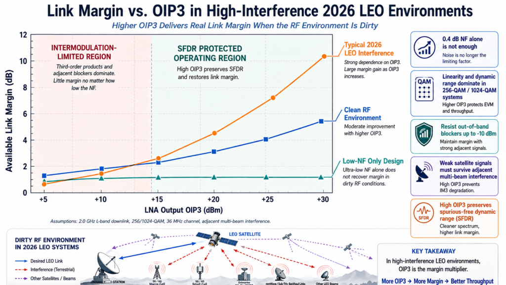
Linearity and dynamic range have officially pulled static noise figure down the altar and become the core yardstick for evaluating LNA performance in 2026. Just imagine, in today’s 256-QAM and even 1024-QAM flying everywhere, even if your LNA has achieved a record 0.4dB NF, if its output third-order intermodulation intercept point cannot withstand the spectrum regeneration caused by adjacent multi-beam interference, it is also a scrap. Today’s high-end systems are dead-protecting “spurious-free dynamic range” , so that weak satellite signals will not be overwhelmed by intermodulation products.
Both ground stations and user terminals have to face a cruel reality: the overflow of 5G/6G ground signals makes the RF environment extremely “dirty”. Now to get a solid G/T index, your LNA must have the ability to resist up to -10 dBm out-of-band blocking signals, and you can’t expect to plug in those bulky filters.
2026 Benchmarking Table: GaAs vs. GaN vs. InP in Ka-Band LNA Applications
| Semiconductor Technology | Gain | Noise Figure (NF) | OIP3 (Linearity & Power) | Radiation Hardness & Survivability | 2026 Market Position & Architecture Notes |
| GaAs (Gallium Arsenide) | Moderate | Compromised (System NF suffers a 0.3–0.5 dB penalty due to required limiter) | Moderate | Low (Vulnerable to high-power radars/jammers; strictly requires high-loss protection limiters) | Legacy / Phased Out Replaced by GaN in high-survivability scenarios. |
| GaN (SiC-based GaN) (150nm & 100nm) | High | Excellent (Limiter-free architecture directly saves 0.3–0.5 dB insertion loss) | Highest (Domineering high-power processing capability) | Excellent (High breakdown voltage yields a top-tier survival rate without limiters) | Mass Deployment Leader Unbeatable cost-performance for massive low-rail terminal shipments. |
| InP (Indium Phosphide) | Very High | Absolute Best (The “Undisputed King”, touching the physical limits of low noise) | Low to Moderate | Low (Fragile architecture; cannot withstand high-power jamming without protection) | Niche / Premium Used only where absolute ultimate low noise is prioritized over cost/power. |
Semiconductor Route Debate In 2026 Architecture
With its domineering high-power processing capability and survival rate, silicon-carbon-based gallium nitride has firmly taken the top spot in the Ka-band LNA industry in 2026. In the past, when GaAs was used, in order to prevent high-power signal from burning down the circuit, a limiter with high loss had to be added. However, GaN has a high breakdown voltage. This “limitless” architecture directly saves the insertion loss of 0.3 to 0.5dB of the protection circuit and pulls down the noise figure of the system as a whole.
Of course, if you want to touch the physical limit of low noise, indium phosphide is still the undisputed king. However, GaN’s cost performance is too good for low-rail terminals that need massive shipments-especially with breakthroughs in 150 nm and 100 nm gate processes, GaN is definitely the best choice for mass deployment in 2026.
Three Concealed Fatal Injurations In Satcom RF Design
The first pit, ignoring the “gain ripple” caused by extreme thermal cycling. This is the most common cause of LEO constellation link instability. The satellite drilled from the shadow area to the direct sun area, and the temperature difference soared to 100°C in just a few minutes. Without active temperature compensation, the gain of ordinary LNA will jump like a roller coaster, forcing the modem’s AGC to find a balance point everywhere, and finally the bit error rate will soar.
The second pit, the power supply rejection ratio design is too rough. High-end LNAs that cost a lot of money are often destroyed on this. The satellite platform space is small, and the noise of the high-frequency switching power supply is very easy to get into the drain power supply of the LNA. If the PSRR of the LNA is not high enough, or if it is not equipped with a special ultra-low noise LDO, then your operation is equivalent to directly pouring phase noise into the signal chain.
The third pit, “input matching trap”. This usually manifests itself as sacrificing noise matching for the sake of standing wave ratio. Novice radio frequency adjustment often hits the perfect 50 ohm match, but in the design of Satcom LNA, the impedance to achieve the lowest noise and the impedance to achieve the maximum power transmission are almost never the same thing. How do 2026 veterans play? They will use balanced amplifier topology or add isolators to stabilize the system, and then nail the LNA to the best noise matching point.
3D RF Performance Cube
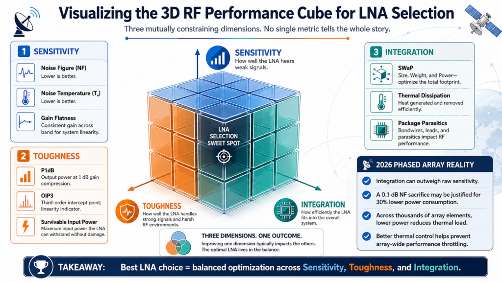
Purchasing complex Satcom devices is huge, so we have introduced the concept of “3D RF performance Rubik’s Cube” internally. Breaking the previous one-dimensional thinking that only focuses on the size of the parameter table ratio, we use the 3 dimension of mutual restraint to consider the LNA:
- Sensitivity dimensions: noise figure, noise temperature, and gain flatness.
- Toughness dimensions: P1dB, OIP3, and input power of survival.
- Integration dimensions: SWaP, heat dissipation capability, and package parasitics.
For example, in the 2026 phased array antenna project, the weight of “integration” absolutely crushed “sensitivity”. We often do one thing: we would rather sacrifice a noise figure of 0.1dB in exchange for a 30% drop in power consumption. After all, in an array of
SWaP-C And Consistency
For the VHTS system in 2026, the “antenna in package” technology that encapsulates the LNA and antenna elements is already standard. You should know that every extra 1mm of microstrip line between the antenna feed and the LNA will bring front-end loss, and about every 1dB loss will increase the noise by about 0.1dB. Now everyone is playing flip-chip solder bumps and wafer-level packaging (WLP), completely killing bonding wires and old connectors, which is equivalent to abruptly “robbing” nearly 1dB from the system-level noise figure.
As for those giant constellations with thousands of satellites, the killer of the cost reduction lies in the CMOS-compatible silicon-based gallium nitride process. Yes, silicon-carbon-based thermal conductivity is indeed better, but silicon-based GaN has a unique skill: it can make digital control logic and LNA directly on the same Die. This enables real-time autonomous calibration of gain and phase-a capability that is needed in the face of extremely complex beamforming requirements in 2026.

FAQs
Q1: It’s 2026. Is the industry benchmark for Ka band still 0.5dB noise figure?
Honestly, for the letter-pass stations on the ground, yes. However, for the low-orbit receiver in the sky, everyone actually prefers the combination of 0.8dB NF plus ultra-high OIP3. Due to the existence of atmospheric background noise and “sky noise” at a specific elevation angle, the gap between 0.5dB and 0.8dB has been smoothed out a lot, but the ability to carry interference has become the key to success or failure.
Q2: How much does the phase noise of LNA affect the high-order modulation of 1024-QAM?
Looking at the LNA alone, its own phase noise and local oscillator are simply insignificant compared. However, the point of the pit people is that the additive white Gaussian noise brought by the inferior LNA will greatly reduce the signal-to-noise ratio, which is macroscopically equivalent to the constellation diagram to “squeeze” the points smaller, resulting in the entire system becoming extremely sensitive to phase jitter.
Q3: The noise of GaN LNA is obviously larger than that of GaAs. Why can it catch fire in the Weitong circle?
Because we’re looking at “system-level NF”. GaN is extremely durable and can eat a lot of input power, so you can completely throw away the front limiter. Calculate an account: a GaAs LNA with 0.5dB NF and a limiter with 0.5dB loss, the system NF is 1.0dB; For a GaN LNA with 0.8dB NF and no sleeve, the system NF is 0.8dB. GaN won 0.2dB directly.
Q4: What is the concept of “group delay” for broadband Satcom LNA?
In the common 2GHz ultra-wide channel in 2026, the nonlinear group delay in LNA will cause different frequency components in the signal to “queue up” for different times. What is the result? Intersymbol Interference. In the current high-end LNA, if the group delay fluctuation in the band cannot be suppressed within 50 picoseconds, it cannot be taken at all.
Q5: How can LNA not be self-excited in the extremely low temperature environment of deep space exploration?
The temperature drops, the gain of the transistor skyrocketed. An LNA that is stable at 25 ℃ at normal temperature is likely to become an oscillator directly at -150 ℃. This requires us to stick to the “stability circle” during the simulation phase, and we must ensure that the stability factor K of the LNA in the entire deep and low temperature range is always greater than 1.
Q6: Do you dare to use COTS LNA for the 2026 satellite mission?
Dare to use, but the premise is that must go through peeling cramp like “up matching screening”. The total ionizing dose test and the single particle effect analysis cannot be less. In fact, many LEO operators in 2026 have adopted a large number of commercial GaN LNA, but they will superimpose their own unique radiation hardening layout technology on the board level design.